Over 50,000 hot-selling automation module components.
ControlLogix Power Supply Sizing Guide

ControlLogix Power Supply Sizing Guide | Powergear X Automation

How to Optimize Allen-Bradley ControlLogix Power Supply Sizing for Maximum Uptime

In the world of industrial automation, few errors are as frustrating as intermittent system resets. Engineers often blame software bugs or faulty modules. However, experienced integrators know that improper power sizing is the real culprit. A ControlLogix system powers a plant’s most critical operations. Therefore, calculating electrical loads accurately is not just a best practice; it is a requirement for operational integrity. At Powergear X Automation, we have observed that many field failures stem from a fundamental misunderstanding of backplane current.

ControlLogix Power Supply Sizing Guide

Calculating Power Beyond Simple Slot Counts

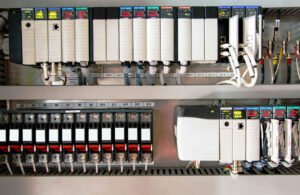
Many technicians mistakenly believe that a 17-slot chassis automatically requires the largest power supply available. In reality, the chassis itself consumes almost no power. The total load depends entirely on the specific modules installed. ControlLogix power supplies, such as the 1756-PA75 or 1756-PB75, provide current to the backplane at specific voltages, primarily 5.1 VDC. To calculate the requirements, you must sum the current draw of every controller, communication bridge, and I/O module listed in their respective datasheets.

Analyzing Module Power Consumption Trends

Modern control systems are becoming increasingly communication-intensive. While a standard digital input module might only draw 0.2 A, a high-performance 1756-EN4TR Ethernet module draws significantly more. Furthermore, motion control and SIL-rated safety modules exert a heavier toll on the backplane. Consequently, a densely packed 7-slot rack running complex motion profiles can easily outdraw a 13-slot rack filled with basic digital I/O. Always prioritize the cumulative amperage over physical space when selecting a PSU.

Implementing the 80% Rule for Long-Term Reliability

Designing a system to run at 100% capacity is a recipe for disaster. Heat is the primary enemy of electronics in factory automation. As temperatures rise inside a control cabinet, the efficiency of the power supply drops. Therefore, Powergear X Automation recommends a “Safety Margin” of 20% to 30%. If your calculated load is 10 A, you should opt for a supply rated for at least 13 A. This buffer accounts for component aging and prevents nuisance tripping during high-demand startup sequences.

Enhancing System Stability with Proper Installation

Reliable hardware requires professional installation techniques. In high-vibration environments like mining or oil and gas, mechanical stability is crucial. Ensure you use end anchors on both sides of the chassis to prevent module shifting. Additionally, external power quality heavily influences the lifespan of your PLC components. We suggest installing a dedicated surge suppressor upstream. This protects the sensitive backplane electronics from voltage spikes caused by large motors or variable frequency drives (VFDs).

Managing Redundant Power Architectures Correctly

Redundancy offers a false sense of security if not maintained. For mission-critical DCS or PLC applications using the 1756-PAR2 system, monitoring is essential. Many engineers forget to map the diagnostic bits into their HMI screens. As a result, a secondary power supply might fail unnoticed, leaving the system with zero redundancy. We recommend periodic “pull-the-plug” tests during scheduled shutdowns. This ensures the switchover mechanism functions perfectly under real-world conditions.

Engineering Technical Requirements Checklist

  • Calculate total current draw at 5.1 VDC and 24 VDC.
  • Verify that the PSU supports the chassis series.
  • Maintain a 25% overhead for future I/O expansion.
  • Install dedicated circuit breakers for the PLC rack.
  • Use shielded cables for high-density analog modules.
  • Check airflow clearance around the power supply heat sinks.

Real-World Application Scenario: High-Speed Packaging

In a recent high-speed bottling line project, the client experienced random “Major Fault” errors on their 1756-L83E controller. Our audit revealed the 10-slot chassis was running at 92% power capacity. Every time the high-speed counters peaked, the voltage dipped slightly. By upgrading from a 1756-PA72 to a 1756-PA75, we eliminated the downtime entirely. For more expert insights and high-quality components, visit Powergear X Automation to find the right solutions for your facility.

Frequently Asked Questions (FAQ)

Q1: Can I mix different brands of power supplies with my ControlLogix chassis?
No. The ControlLogix backplane uses a proprietary physical connection. You must use Rockwell-compatible 1756 power supplies to ensure electrical safety and warranty compliance.

Q2: How often should I replace my PLC power supplies proactively?
In standard factory environments, we recommend replacement every 7 to 10 years. In high-heat or high-vibration areas, consider a 5-year replacement cycle to prevent unexpected electrolytic capacitor failure.

Q3: Does the number of empty slots affect my power calculation?
Empty slots do not consume power. However, they represent potential future load. When sizing your PSU, always account for the modules you plan to add next year, not just what is in the rack today.

Troubleshooting AB PLC Non-Recoverable Faults: A Field Guide

How to Export & Analyze Allen-Bradley Non-Recoverable Major Faults

Troubleshooting Allen-Bradley Non-Recoverable Major Faults: A Diagnostic Guide

The Critical Role of the PLC Fault Log

In industrial automation, a “Non-Recoverable Major Fault” signal usually means production has already halted. Consequently, the controller’s fault log becomes your most valuable diagnostic asset. Engineers must export this data to distinguish between firmware corruption and hardware failure. Moreover, accurate logs support Root Cause Analysis (RCA) and help meet regulatory standards like FDA 21 CFR Part 11. Without this data, maintenance teams often waste hours guessing the cause of unplanned downtime.

Troubleshooting AB PLC Non-Recoverable Faults: A Field Guide

Understanding Fault Types and Code Granularity

Allen-Bradley systems, including ControlLogix and CompactLogix, categorize errors by Type, Code, and Extended Code. These specifics are vital because a non-recoverable fault often indicates a deep hardware or firmware conflict. For example, my field experience shows that electrostatic discharge (ESD) often triggers memory corruption. While front-panel LEDs might show a generic red light, the exported log reveals the specific memory address failure. Therefore, granular data is essential for preventing repeat occurrences in high-stakes factory automation environments.

Protecting Data in Volatile Controller Memory

Controllers store fault logs in volatile memory, which clears if the system loses power. To prevent data loss, I highly recommend installing a non-volatile memory module, such as the 1784-SD2. This hardware ensures the fault history survives a power cycle or a complete CPU reset. In continuous-process industries, losing this history can extend the Mean Time to Repair (MTTR) significantly. Furthermore, a permanent record is necessary for compliance audits in pharmaceutical or chemical plants.

Navigating Studio 5000 Compatibility Issues

Exporting a detailed fault log requires the correct version of Studio 5000 Logix Designer. If you use a mismatched software version, you might go online but miss critical “Extended Code” details. Always ensure your workstation software version matches or exceeds the controller’s major firmware revision. In addition, maintaining a multi-version installation on your engineering laptop prevents “diagnostic blind spots” when working with legacy control systems.

A Field-Proven Workflow for Exporting Logs

When a fault occurs, follow a disciplined technical process to ensure you capture every detail. Do not rush to clear the fault immediately, as this erases the evidence needed for a permanent fix.

  1. Establish a secure connection using Studio 5000 Logix Designer.
  2. Navigate to Controller Properties and select the Major Faults tab.
  3. Record the specific Fault Type, Code, and Extended Code.
  4. Select Tools then Save Project with Fault Information.
  5. Capture screenshots of the Diagnostics tab for additional context.

Practical Maintenance Insights from the Factory Floor

In high-EMI (Electromagnetic Interference) environments, “Non-Recoverable” faults often stem from poor grounding rather than a defective CPU. Before replacing expensive hardware, I suggest inspecting surge suppression and backplane integrity. If a controller faults repeatedly after power cycles, the power supply is the most likely culprit. Powergear X Automation experts often find that replacing the power supply solves 30% of persistent non-recoverable errors without needing a new processor.

The Powergear X Automation Perspective on Reliability

At Powergear X Automation, we believe that data-driven maintenance is the backbone of modern industrial reliability. We often see teams replace CPUs prematurely due to a lack of diagnostic clarity. By integrating non-volatile memory and robust firmware version control, you create a more resilient control system. If you are looking to upgrade your legacy systems or need high-quality replacement modules, our team provides the technical expertise to ensure your hardware choices match your operational needs.

Application Scenario: Resolving Intermittent Backplane Failures

In a large-scale pharmaceutical packaging line, a ControlLogix CPU reported a non-recoverable fault every 48 hours. By exporting the fault log, the engineering team identified “Type 01 Code 01” errors, which pointed to backplane communication issues. Instead of replacing the CPU, they discovered a loose 1756-A10 chassis mounting bolt causing intermittent grounding issues. This discovery saved the plant over $10,000 in unnecessary hardware costs.

Frequently Asked Questions (FAQ)

1. Does a non-recoverable fault always require a hardware replacement?
No, it does not. Statistics suggest nearly 50% of these faults result from power quality issues or firmware glitches. Always analyze the “Extended Fault Code” before purchasing new components.

2. What is the most common mistake made during an emergency fault event?
The most common error is clearing the fault or cycling power before exporting the log. This action permanently deletes the diagnostic breadcrumbs needed for a true root cause analysis.

3. How can I ensure my fault logs are preserved during a total power failure?
You should equip every mission-critical Allen-Bradley PLC with an industrial-grade SD card (non-volatile memory). Configure the controller to store “Project and Fault” data to the card on every major fault event.

Back to Top
Product has been added to your cart