Over 50,000 hot-selling automation module components.

A Comprehensive Guide to Allen-Bradley ControlLogix Processor: Features & Benefits

Introduction

Hello there! As an engineer with years of experience in the industrial control field, I’ve had my hands on countless systems. When it comes to high-performance and reliable controllers, the Allen Bradley ControlLogix processor is always a top contender. I’ve seen firsthand how these processors can transform a factory floor, and I’m excited to share a detailed guide with you. This article will help you understand the key features and benefits of ControlLogix, and why it might be the perfect fit for your next automation project.

Allen-Bradley ControlLogix Processor

What is a ControlLogix Processor?

Simply put, a ControlLogix processor is a powerful Programmable Automation Controller (PAC). Unlike a traditional Programmable Logic Controller (PLC), a PAC offers more advanced features. It combines logic, motion, process control, and safety in a single platform. This “one-stop-shop” approach is a game-changer. Instead of juggling multiple controllers, you can manage everything from one unified system. This simplifies your hardware, reduces complexity, and makes your life much easier.

Key Features of the ControlLogix Platform

The magic of ControlLogix lies in its unique architecture. It’s built on a core foundation that sets it apart.

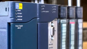
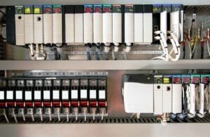
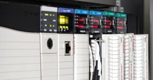
  • Modular and Scalable: This is a huge benefit. The ControlLogix chassis is a backplane where you can plug in different modules. Need more I/O? Just add a new module. Want to add a motion control card? Plug it in. This modular design means your system can grow with your needs. You don’t have to replace the whole controller when your requirements change.
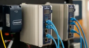
  • Integrated Communication: ControlLogix uses a unified network, primarily EtherNet/IP. This allows all devices—the processor, I/O modules, drives, and HMI (Human Machine Interface)—to communicate seamlessly. This integrated approach reduces the hassle of setting up different networks and makes troubleshooting much more straightforward.
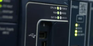
  • High Performance: ControlLogix processors are known for their speed and processing power. They can handle complex applications with ease, making them ideal for high-speed manufacturing, process control, and intricate motion control tasks. This performance ensures your operations run smoothly and efficiently, minimizing downtime.
  • Powerful Programming Environment: The Studio 5000 Logix Designer software is the brain behind the operation. This software lets you program and configure all aspects of the ControlLogix system. It’s a powerful tool that uses a common programming language across the entire platform, which means you only need to learn one tool to manage everything.

Real-World Benefits You’ll See

So, what do all these features mean for you and your business?

  • Reduced Engineering Time: Because of the unified software and integrated platform, you spend less time configuring and programming. This means your projects get completed faster and more efficiently.
  • Lower Total Cost of Ownership: While the initial investment might seem higher, the long-term savings are significant. With a scalable system, you only buy what you need. Simplified maintenance and faster troubleshooting also save you money over time.
  • Improved Productivity: The high performance and reliability of ControlLogix mean your machines run faster and more consistently. Less downtime and higher throughput lead to increased productivity and profitability.
  • Enhanced Safety and Security: ControlLogix offers integrated safety solutions that are certified for use in critical applications. This means you can build a safer system for your employees and meet strict industry standards.

Allen-Bradley ControlLogix Processor

Final Thoughts: My Unique Perspective

From my years in the field, I’ve seen many systems come and go. The ControlLogix platform has stood the test of time because of its reliability and flexibility. What I truly appreciate is how it simplifies the complex world of industrial automation. It’s not just a product; it’s a foundation for building a robust and efficient control system that can adapt to future challenges.

If you are looking to upgrade your control system or start a new project, I highly recommend considering the ControlLogix platform.

Ready to find the right components for your system? Click the link below to explore the high-quality Allen Bradley ControlLogix products available from Powergear X Automation Limited.

ModelTitleLink
1756-L72Allen-Bradley ControlLogix 1756-L72 Processor (4MB Memory)Learn More
1756-L75Allen-Bradley ControlLogix 1756-L75 ControllerLearn More
1756-OA16Allen-Bradley ControlLogix 1756-OA16 AC Input ModuleLearn More
1756-ENETAllen-Bradley ControlLogix 1756-ENET Ethernet ModuleLearn More
1756-L73Allen-Bradley ControlLogix 1756-L73 Processor (8MB Memory)Learn More
Understanding Fault Detection and Diagnostics in PLC DCS Systems

Understanding Fault Detection and Diagnostics in PLC & DCS Systems

Introduction

Welcome! As a seasoned engineer in industrial automation, I’ve seen firsthand how critical it is to quickly find and fix problems. In our world, where systems run 24/7, a small issue can quickly become a big headache. That’s where Fault Detection and Diagnostics (FDD) comes in. FDD isn’t just a fancy term; it’s a powerful set of tools and methods we use to keep things running smoothly. This guide will walk you through what FDD is, why it’s so important, and how you can use it effectively in your PLC and DCS systems.

Understanding Fault Detection and Diagnostics in PLC DCS Systems

What is Fault Detection and Diagnostics (FDD)?

At its core, FDD is the process of automatically identifying when something is wrong (detection) and then figuring out exactly what and where the problem is (diagnostics).

  • Fault Detection is like a security guard. It watches the system for any unusual behavior. For example, it might notice a motor drawing too much current or a temperature sensor giving a strange reading. The goal is to spot these anomalies before they cause a full shutdown.
  • Fault Diagnostics is the detective work. Once a fault is detected, this part of the process figures out the root cause. It answers questions like: “Is the sensor broken?” or “Is the valve stuck?” This helps maintenance teams fix the right thing the first time, saving a lot of time and effort.

Why Is FDD So Important for Your Systems?

Many people think FDD is a “nice-to-have” feature, but I believe it’s essential. My own experience has taught me that strong FDD leads to three key benefits:

  • Reduced Downtime: The biggest benefit is less unplanned downtime. When a system can tell you exactly what’s wrong, you don’t have to waste hours troubleshooting. You can go straight to the problem, fix it, and get back online faster. This directly impacts your bottom line.
  • Improved Safety: Many faults, if left unchecked, can create dangerous conditions. FDD helps you catch these issues early. For example, detecting a pressure sensor failure can prevent a potential over-pressure situation in a vessel, protecting both equipment and personnel.
  • Predictive Maintenance: Instead of waiting for something to break, FDD helps you move toward predictive maintenance. By tracking trends and small anomalies over time, you can schedule repairs before a component fails. This is a game-changer, allowing you to perform maintenance on your schedule, not your system’s.

Common FDD Methods and My Unique Insights

There are many ways to implement FDD. Here are some of the most common, along with some practical advice I’ve picked up over the years:

  • Alarming and Thresholds: This is the most basic form of FDD. We set up alarms to trigger when a value goes above or below a certain point. My advice here is simple but crucial: don’t overdo it. Too many alarms can lead to “alarm fatigue,” where operators start to ignore them. Focus on creating meaningful, prioritized alarms.
  • Logical Checks: This involves using programming logic within the PLC or DCS to verify sensor inputs. For example, if a pump is off, its flow sensor should read zero. If it doesn’t, you have a fault. My unique perspective is to always add a simple time delay to these checks. A momentary glitch shouldn’t trigger a full alarm.
  • Pattern Recognition: This is a more advanced technique where the system looks for specific patterns that indicate a fault. For instance, a valve that takes longer and longer to open might be getting stuck. This requires a bit more programming but can catch problems that simple thresholds miss. I recommend starting with critical components and expanding from there.

Moving Forward with FDD

Implementing a solid FDD strategy isn’t a one-time task; it’s an ongoing process. Start small, perhaps with a single critical machine, and then expand your efforts. The goal is to build a smarter, more resilient control system. The investment in FDD always pays off in the long run.

Ready to upgrade your system’s reliability and efficiency? We have the right tools and solutions to help you get started. Powergear X Automation Limited specializes in industrial control solutions designed for maximum uptime and performance.

👉 Click here to explore our products and take the first step towards a smarter, more reliable operation.

How to Optimize Your PLC Code for Maximum Performance and Reliability

Boosting Efficiency: How to Optimize Your PLC Code for Maximum Performance and Reliability

Introduction

Hello, fellow automation enthusiasts! I’m here to share some practical advice on a topic that’s critical to our work: writing efficient and reliable PLC code. As someone who’s spent years in the field, I know that good code doesn’t just work—it works well. It’s clean, easy to maintain, and performs flawlessly under pressure. In this guide, I’ll walk you through some key strategies to get the most out of your PLC systems, sharing a few unique insights I’ve picked up along the way.

How to Optimize Your PLC Code for Maximum Performance and Reliability

1. Simplify Your Logic: The “KISS” Principle

The “Keep It Simple, Stupid” (KISS) principle is a golden rule in PLC programming. Complex code is hard to troubleshoot and slow to execute. My advice? Break down complex processes into smaller, manageable subroutines or functions. Use simple, direct logic wherever possible. Instead of a single, sprawling routine with hundreds of rungs, create multiple, well-named routines for specific tasks like “Motor Control,” “Safety Interlocks,” or “HMI Communication.” This makes your code more readable and your system easier to debug.

2. Optimize Data Handling: Efficient Memory Management

Memory isn’t infinite, and how you use it directly impacts performance. One common mistake is using a mix of data types when a single type would suffice. For example, if you’re working with a set of boolean values, don’t use 16 separate INT variables. Use a single DINT or DWORD and manage the individual bits. This reduces memory usage and speeds up data access. Another tip: use structured text (ST) for mathematical calculations. It’s often more efficient and easier to read than a long chain of ladder logic rungs for complex math.

How to Optimize Your PLC Code for Maximum Performance and Reliability

3. Prioritize Your Scan Time: The Key to Reliability

The PLC scan time is the loop that executes your program. A long scan time can lead to missed events and system instability. To keep it short and consistent, avoid using a single, large program file. Use function blocks and subroutines to organize your code and, most importantly, execute code only when it’s needed. For example, use a trigger or a flag to call a complex diagnostic routine only after a fault has occurred, not on every scan. Also, be mindful of using indirect addressing or complex loops within your main scan, as these can add significant, unpredictable delays.

4. Unique Insight: Don’t Just Write Code, Write “Future-Proof” Code

This is my personal philosophy: write code for the next person who has to work on it, and that person might be you in five years. This means adding clear comments, using descriptive tag names (e.g., Motor1_Run_CMD instead of M1_R_C), and creating a consistent coding standard. My unique take is to document not just what the code does, but also why it does it. Explain the design choices and the logic behind them. This “why” documentation is invaluable for troubleshooting and modifications down the road, and it’s a practice many people overlook.

In Conclusion: The Path to Better Automation

Writing great PLC code is a skill that develops with experience and a commitment to best practices. By simplifying logic, optimizing data, managing scan time, and embracing a “future-proof” mindset, you can create systems that are not only efficient and reliable but also a pleasure to work with.

Ready to take your automation projects to the next level? Explore the robust and innovative solutions from Powergear X Automation Limited.

👉 Click here to check out our latest products and see how our hardware can complement your expertly crafted code!

Maximizing Performance with Allen-Bradley Kinetix 300

Maximizing Performance with Allen-Bradley Kinetix 300: A Step-by-Step Setup Guide

Introduction

The Foundation: Hardware and Software Setup

Before we do anything, let’s get the basics right. A good start makes everything else easy.

Mounting and Wiring

This might sound simple, but it’s crucial. Ensure the drive is mounted in a cabinet with proper airflow. Heat is the enemy of electronics. When wiring, pay close attention to the manual. I’ve seen countless hours wasted because of a simple wiring mistake. Make sure your power, motor, and feedback cables are correctly terminated and shielded to prevent electrical noise.

Maximizing Performance with Allen-Bradley Kinetix 300

Software Installation

You’ll need the Studio 5000 Logix Designer and DriveTools SP. Make sure you have the latest versions. Compatibility issues between software and firmware are a common headache. My tip? Always check the Rockwell Automation Product Compatibility and Download Center (PCDC) before you start. It saves so much time later.

Getting Connected and Configuring the Drive

Now that the physical setup is done, let’s talk about the digital side. This is where the magic happens.

Establishing Communication

Connect your PC to the Kinetix 300 via an Ethernet cable. Open Studio 5000 and add the drive to your project’s I/O configuration. The Kinetix 300 uses EtherNet/IP, which makes this part very straightforward. Make sure your IP addresses are set up correctly. A unique IP for each device is a must.

Drive Configuration

Once connected, open DriveTools SP. Here’s where you input all your motor and application data. Don’t guess here. Use the motor’s nameplate data. The Kinetix 300 has a powerful auto-tuning feature, but it works best with accurate information. My unique insight? I’ve found that manually inputting the motor’s inertia can sometimes give you a better starting point than letting the software guess.

The Power of Tuning and Optimization

This is the most important step for maximizing performance. A poorly tuned drive can lead to shaky motion, overshoot, and instability.

The Auto-Tune Feature

The Kinetix 300’s auto-tune is an excellent starting point. It calculates the basic PID (Proportional, Integral, Derivative) values for your system. Run this feature with the motor disconnected from the load first, if possible. This gives a clean, accurate baseline.

Manual Tuning (Pro Tip)

After auto-tuning, you often need to fine-tune the system. I always start with the Proportional Gain (Kp). Increase it slowly until you see the motor start to oscillate, then back off a bit. Next, add some Integral Gain (Ki) to eliminate any steady-state error. Finally, use a small amount of Derivative Gain (Kd) to dampen any overshoot. My secret? Use the Trend tool in Studio 5000 to visualize the motion profile. It’s the best way to see what’s happening and make precise adjustments.

Conclusion: Achieving Peak Performance

By following these steps, you’ll go from a basic setup to a high-performance system. The Allen-Bradley Kinetix 300 is a robust and capable drive. The key to unlocking its full potential is a careful, systematic approach. Getting the hardware and software basics right, configuring the drive accurately, and taking the time to fine-tune your application will result in smooth, precise, and reliable motion.

Remember, a well-tuned system is a happy system. It reduces wear and tear, increases efficiency, and makes your machine more productive.

Ready to start your next project? We have the Allen-Bradley Kinetix 300 and all the necessary accessories you need.

Click here to explore our full range of Allen-Bradley Kinetix products at Powergear X Automation Limited!

PowerFlex 40P AC Drive

Achieving Seamless DCS Communication with Allen-Bradley PowerFlex 40P Drives

Introduction

Integrating PowerFlex 40P VFDs into Distributed Control Systems enables centralized command, real-time monitoring, and optimized industrial automation. This guide provides expert strategies for reliable DCS-drive communication.

The Importance of Seamless Integration

Proper integration delivers:

  • Centralized control of drive operations
  • Real-time diagnostic data for predictive maintenance
  • Process optimization through continuous monitoring
  • Reduced unplanned downtime

Pro Tip: Plan for long-term data analysis during initial integration – collect parameters that enable future predictive maintenance.

PowerFlex 40P AC Drive

PowerFlex 40P AC Drive

Choosing the Right Communication Protocol

Select based on existing infrastructure and data requirements:

  • EtherNet/IP:
    • Preferred for modern systems
    • High-speed tag-based communication
    • Simplified data mapping
  • Modbus RTU/TCP:
    • Ideal for existing Modbus infrastructure
    • Verify native DCS driver compatibility
  • DeviceNet:
    • Suitable for legacy systems
    • Less common in new installations

Selection Criteria: Prioritize future expansion capabilities and data volume requirements.

Configuring the PowerFlex 40P Drive

Critical setup steps:

  • Set unique IP addresses (EtherNet/IP/Modbus TCP)
  • Configure matching baud rate/parity (Modbus RTU)
  • Set control source to “Comm Port” or “Network”
  • Define network-based reference source

Pro Tip: Use Rockwell’s Connected Components Workbench (CCW) for efficient configuration and ladder logic generation.

DCS Configuration and Tag Mapping

DCS-side implementation:

  1. Add drive as hardware device per DCS vendor specs
  2. Create communication tags for:
    • Run/Stop commands
    • Speed reference/actual speed
    • Current draw and fault status
  3. Develop control logic for command execution

Best Practice: Standardize tag naming conventions across all equipment for easier troubleshooting and expansion.

Testing and Troubleshooting

Validation methodology:

  • Start with basic commands (Run/Stop)
  • Progress to advanced operations (speed control)
  • Monitor DCS and drive displays concurrently

Troubleshooting Guide:

IssueDiagnostic Steps
Network ConnectivityPerform ping tests (Ethernet)
Communication FailureVerify wiring termination/shielding
Parameter MismatchCross-check drive/DCS settings
Error CodesConsult PowerFlex 40P manual

Unique Insight: Conduct “cold start” tests (full power cycle) to identify initialization timing issues.

Conclusion

Seamless PowerFlex 40P-DCS integration requires protocol selection precision, meticulous configuration, and comprehensive testing – delivering robust industrial control systems with enhanced operational visibility.

Ready to enhance your industrial automation? Explore Powergear X Automation Limited’s compatible solutions for Allen-Bradley PowerFlex drives

Step-by-Step Setup Guide for Allen-Bradley PowerFlex 40P AC Drives in Industrial Automation

Step-by-Step Setup Guide for Allen-Bradley PowerFlex 40P AC Drives in Industrial Automation

Welcome, fellow engineers! This practical guide walks you through setting up Allen-Bradley PowerFlex 40P AC Drives, sharing hands-on insights for efficient commissioning in industrial systems.

Understanding the PowerFlex 40P: My Perspective

The PowerFlex 40P delivers exceptional balance between features and simplicity. Its sensorless vector control and compact design make it ideal for applications requiring precise speed control without encoder feedback, especially where panel space is limited.

Essential Pre-Installation Checks

Critical preparations before wiring:

  • Power Verification: Confirm voltage/current ratings match supply – check nameplate to prevent damage
  • Environment: Ensure clean, dry, cool location – avoid dust, moisture and excessive heat
  • Motor Compatibility: Verify motor HP, voltage, and current ratings match drive capabilities

Wiring the PowerFlex 40P: Practical Tips

Power Wiring (L1/L2/L3 to T1/T2/T3):
Use oversized wires for better current handling and heat dissipation. Connect AC power to L terminals and motor to T terminals.

Control Wiring:

  • Separate control wires from power cables to prevent noise interference
  • Always use shielded cables for analog signals

Grounding Protocol:
Connect ground terminal directly to earth ground – critical for safety and noise reduction.

Allen-Bradley PowerFlex 40P Frequency Drive

Basic Configuration and Parameter Setup

Initial Power-Up:
After securing connections, apply power – keypad should illuminate.

Motor Data Entry:
Set these parameters precisely from motor nameplate:

  • P031 [Motor NP Volts]
  • P033 [Motor NP Amps]
  • P034 [Motor NP Freq]
  • P035 [Motor NP RPM]

Control Source Selection:
Configure A041 [Start Source A] for keypad (initial testing), digital inputs (PLC), or analog input.

Speed Reference Scaling:
For analog inputs:

  • Set P038 [Analog Input 1 Sel]
  • Scale with A051 [Anlg In1 Scale Lo] and A052 [Anlg In1 Scale Hi]

Advanced Considerations and Troubleshooting

Auto-Tune Optimization:
Execute P040 [Motor Auto Tune] to measure motor characteristics for peak performance.

Acceleration/Deceleration:
Balance P044 [Accell Time 1] and P045 [Decel Time 1] to avoid trips or sluggish operation.

Fault Management:
Interpret common codes – address root causes of overcurrent, overvoltage, and ground faults.

Preventive Maintenance:

  • Keep cooling fins dust-free
  • Regularly check terminal tightness

Conclusion: Empowering Your Industrial Automation

Mastering PowerFlex 40P setup requires attention to wiring detail, accurate parameter entry, and proactive troubleshooting – essential skills for robust automation systems.

Ready to upgrade your industrial control systems? Click here to explore Allen-Bradley PowerFlex 40P AC Drives and automation solutions from Powergear X Automation Limited.

Exploring the Compatibility of GE Fanuc PACSystems RX3i with Legacy Systems

Integrating Bently Nevada 9200 Velocity Data into Your Existing PLC/DCS Alarm Strategy

Introduction

As an operations manager and engineer with years of experience in industrial automation, I’ve seen firsthand the challenges of managing disparate systems for predictive maintenance. You’ve invested in vibration monitoring with Bently Nevada 9200 velocity sensors, and your plant runs on a robust PLC/DCS. The next logical step is to bridge the gap between them, creating a unified alarm strategy that simplifies operations and boosts efficiency.

Integrating 9200 Velocity Data into PLC/DCS Alarm Strategy

Integrating 9200 Velocity Data into PLC/DCS Alarm Strategy

Why Integrate? The Power of a Unified View

Integrating your Bently Nevada 9200 velocity data directly into your PLC/DCS offers significant advantages. Currently, you might be relying on separate software or manual checks to interpret vibration data. This creates silos of information and can lead to delayed responses to critical equipment issues.

  • Centralized Alarm Management: All your alarms, from process deviations to vibration anomalies, appear in one place.
  • Improved Decision-Making: Operators gain immediate access to vital equipment health data.
  • Reduced Training Burden: Eliminates the need for teams to learn new software interfaces.
  • Enhanced Automation Opportunities: Develop sophisticated control strategies like soft shutdowns based on vibration levels.
  • Cost Savings: Prevent catastrophic failures through early detection.

Overcoming Integration Hurdles: A Practical Approach

Integrating specialized vibration monitoring systems with standard control systems can seem daunting. However, it’s often more straightforward than you think.

  • Identify Available Outputs: Confirm analog outputs from your Bently Nevada 9200 system.
  • Select PLC/DCS Analog Inputs: Dedicate appropriate analog input modules.
  • Scaling and Calibration: Scale incoming 4-20mA signals to represent actual vibration units.
  • Alarm Logic Configuration: Configure warning and critical alarms based on vibration limits.
  • Human-Machine Interface (HMI) Integration: Display vibration data prominently on HMI screens.

My Unique Take: Beyond Just Alarms

While integrating for alarm management is the primary goal, don’t stop there.

  • Trending and Historical Data: Utilize PLC/DCS data logging to track vibration trends.
  • Integration with EAM: Link PLC/DCS data with Enterprise Asset Management systems.
  • Condition-Based Control: Implement logic for automatic parameter adjustments.
  • Leverage Existing Expertise: Empower control system engineers with proper documentation.

Conclusion: A Smarter Path to Reliability

Integrating your Bently Nevada 9200 velocity data into your existing PLC/DCS alarm strategy is a powerful step towards a more efficient and reliable operation. It consolidates information, empowers your operators, and ultimately reduces unplanned downtime and maintenance costs.

Ready to simplify your predictive maintenance strategy? Powergear X Automation Limited offers the expertise and products you need for seamless integration. Click here to explore our solutions and take the next step toward enhanced plant reliability!

Exploring the Compatibility of GE Fanuc PACSystems RX3i with Legacy Systems

Shielding and Grounding Best Practices for Bently Nevada 991 Transmitters

Stop Signal Noise & PLC/DCS Glitches

Clean data is vital in industrial control systems. As an operations manager, I’ve seen signal noise turn reliable data into headaches, causing PLC/DCS glitches. Your Bently Nevada 991 thrust transmitter’s precision can be ruined by electrical interference. This guide shows essential shielding and grounding practices to ensure rock-solid data.

Shielding and Grounding Best Practices for Bently Nevada 991 Transmitters

Why Signal Noise Threatens Your Operations

Signal noise isn’t just annoying – it’s dangerous. Erratic signals from your 991 transmitter can cause:

  • ⚠️ False alarms and unnecessary shutdowns
  • ⚠️ Missed real machinery problems
  • ⚠️ Corrupted thrust position data

Key Insight: While the 991 is robust, industrial environments aren’t. Motors, VFDs, and communication lines create interference that proper shielding blocks.

Essential Shielding Practices

1. Use Proper Shielded Cables

  • Always use Bently Nevada’s shielded cables
  • Never substitute with unshielded alternatives
  • The braided shield acts like a Faraday cage against noise

2. Smart Cable Routing

  • ↔️ Keep 12+ inches from power cables
  • ⤵️ Cross other cables at 90-degree angles
  • 🚫 Avoid motors, transformers, and welders

3. Regular Cable Inspections

  • Check for nicks, cuts, or crushing
  • Test shield continuity monthly
  • Replace damaged cables immediately

Shielding and Grounding Best Practices for Bently Nevada 991 Transmitters

Mastering Grounding Techniques

The Golden Rule: Single-Point Grounding

  • Ground shield at monitoring end ONLY (PLC/DCS cabinet)
  • Never ground both ends – creates noise antennas
  • Use dedicated instrument ground point

Proper Ground Connections

  • 🔧 Clean contact surfaces thoroughly
  • 🔩 Use star washers for metal-to-metal contact
  • 📏 Check tightness quarterly (vibration loosens connections)

Step-by-Step Installation Guide

  1. Mount Transmitter – Secure on clean surface
  2. Route Cable – Maintain 12″ from power sources
  3. Transmitter Connections – Connect wires (leave shield unconnected)
  4. Monitoring End – Connect to PLC/DCS input card
  5. Ground Shield – Connect only at rack ground bus
  6. Verify – Test shield continuity (grounded at one end only)

Shielding and Grounding Best Practices for Bently Nevada 991 Transmitters

Maintenance & Troubleshooting

Document Everything

Record your grounding scheme – saves hours during troubleshooting

Environmental Checks

Inspect for moisture damage quarterly – degrades insulation

Noise Testing

Use oscilloscopes to visualize interference patterns

Critical Benefits

  • ✅ Eliminate false alarms and shutdowns
  • ✅ Prevent missed machinery failures
  • ✅ Ensure accurate thrust position data
  • ✅ Extend transmitter lifespan
  • ✅ Reduce maintenance costs by up to 40%

Final Recommendation

Proper shielding and grounding aren’t optional – they’re essential for reliable operations. Following these practices ensures your Bently Nevada 991 delivers accurate data, protects turbines, and prevents costly PLC/DCS glitches. The few hours invested in perfecting your setup prevent weeks of troubleshooting.


Get Noise-Free Monitoring – Explore Powergear X Automation’s Bently Nevada Solutions

ModelTitleLink
991-25-70-01-05Bently Nevada 991 Thrust TransmitterLearn More
991-25-50-01-00Bently Nevada 991 Thrust TransmitterLearn More
991-25-70-03-05Bently Nevada 991 Thrust TransmitterLearn More
991-01-XX-01-00Bently Nevada 991 Thrust TransmitterLearn More
Integrating the Bently Nevada 177230 Seismic Transmitter for Immediate Impact Detection

Integrating the Bently Nevada 177230 Seismic Transmitter for Immediate Impact Detection

Introduction

Quick impact detection is vital for industrial safety and machine health. The Bently Nevada 177230 Seismic Transmitter excels at this job. This guide shows how to connect it to your PLC or DCS system. Doing this improves reliability and speeds up response times.

Why Choose the Bently Nevada 177230? My View

Having tested many sensors, the 177230 stands out. It’s tough, accurate, and perfect for harsh industrial places. Its reliable data helps predict maintenance needs and avoid costly stops. What I value most is its simplicity: Easy setup with exact measurements.

Integrating the Bently Nevada 177230 Seismic Transmitter for Immediate Impact Detection

How the 177230 Works

This transmitter measures vibrations and converts them to electrical signals. With its standard 4-20 mA output, it connects easily to PLCs or DCS systems. You get continuous vibration data to set alerts for abnormal activity.

Simple Connection Guide

Follow these steps to connect to your control system:

1. Mounting and Wiring

  • Mounting: Pick a flat, stable spot near your equipment. Clean the surface first. Secure the transmitter firmly – loose mounts cause bad readings.
  • Wiring: Connect the two output wires to your PLC/DCS analog input. Follow the manual’s wiring diagram. Remember correct polarity and power supply.

2. PLC/DCS Setup

  • Scaling: Convert the 4-20 mA signal to vibration units (like mm/s). Use scaling factors from the manual.
  • Alarms: Set vibration limits. Start with manufacturer suggestions, then adjust as you collect data.
  • Logic: Program actions like: Trigger alarms, notify operators, start safe shutdowns, or log data.

3. Testing

  • First Checks: Confirm power and signal reading
  • Test Vibrations: Create small test vibrations. Check if readings match.
  • Alarm Test: Force high vibrations to trigger alarms. Verify responses.

Integrating the Bently Nevada 177230 Seismic Transmitter for Immediate Impact Detection

Key Tips for Success

  • Baseline Matters: Record normal vibration levels before setting alarms
  • Track Trends: Watch slow changes that predict future problems
  • HMI Display: Show vibration data on operator screens
  • Regular Calibration: Maintain accuracy with scheduled checks

Integrating the Bently Nevada 177230 Seismic Transmitter for Immediate Impact Detection

Important Benefits

  • Quick Detection: Spot problems immediately
  • Less Downtime: Prevent major breakdowns
  • Better Safety: Protect workers and machines
  • Smarter Decisions: Use data for maintenance plans

Adding the Bently Nevada 177230 boosts your system’s safety and efficiency. Ready to improve your impact detection?

Click here to explore Powergear X Automation Limited’s Bently Nevada solutions!

ModelTitleLink
177230-00-01-CNBently Nevada 177230 Seismic TransmitterLearn More
177230-00-02-05Bently Nevada 177230 Seismic TransmitterLearn More
177230-01-02-CNBently Nevada 177230 Seismic TransmitterLearn More
177230-02-01-05Bently Nevada 177230 Seismic TransmitterLearn More
177230-02-01-CNBently Nevada 177230 Seismic TransmitterLearn More
Mastering RX3i Diagnostics Troubleshooting

Mastering RX3i Diagnostics & Troubleshooting: How to Slash Mean-Time-To-Repair (MTTR)

Introduction

As an engineer and operations manager with years of experience in industrial control, I know how critical it is to minimize downtime. The RX3i PAC Systems are robust, but even the best systems can encounter issues. The real challenge isn’t preventing problems entirely—it’s fixing them fast. This guide will share my insights on how to slash your Mean-Time-To-Repair (MTTR) when working with RX3i, turning potential headaches into quick fixes.

Mastering RX3i Diagnostics Troubleshooting

Understanding Your RX3i System Inside Out

Before you can troubleshoot, you need to deeply understand your system. This goes beyond just knowing what each module does. It means understanding the interconnections, the expected behavior under normal operation, and the specific failure modes unique to your application. I’ve seen many situations where a lack of foundational knowledge led to hours of wasted troubleshooting.

Leveraging Built-in Diagnostic Tools

The RX3i offers powerful built-in diagnostics. Don’t just scan for faults; understand what each fault code means.

  • PACSystems Machine Edition (PME): This is your primary window into the RX3i. Get familiar with the Reference View and I/O Navigator.
  • Diagnostic Log: The PLC’s diagnostic log is invaluable. It records events and faults with timestamps.
  • Force and Disable: Use these functions cautiously, but master them for testing.

Mastering RX3i Diagnostics Troubleshooting

Strategic Troubleshooting Approaches

I advocate for a systematic approach rather than random trial-and-error.

  • Define the Problem Clearly: What exactly is happening? When did it start? What changed?
  • Isolate the Issue: Is it hardware or software? Input or output? Specific module or entire rack?
  • Check the Simplest Things First: Is the power on? Are cables properly seated? Is a fuse blown?
  • One Change at a Time: When you’re making adjustments, change only one thing and then re-test.
  • Documentation is Key: Keep up-to-date schematics, logic diagrams, and maintenance logs.

My Unique Insights: Beyond the Manual

  • The “Hunch” Factor: While systematic, don’t dismiss your gut feeling.
  • Network Diagnostics as a First Step: In modern systems, network issues often mimic PLC faults.
  • The Power of Peer Collaboration: Don’t be afraid to ask for help.
  • Preventive Diagnostics: Don’t wait for a failure. Monitor key parameters, track module health, and perform routine checks.

Why Slash MTTR? It’s About More Than Just Repair Time

Reducing MTTR isn’t just about how quickly you fix a machine. It impacts overall productivity, operational costs, and even safety. Faster repairs mean less lost production, lower labor costs for maintenance, and reduced risk of secondary damage or safety incidents. It directly contributes to your bottom line.

Conclusion: Investing in Knowledge Pays Off

Mastering RX3i diagnostics and troubleshooting is an ongoing process. It requires a blend of technical knowledge, systematic thinking, and practical experience. By understanding your system, leveraging its diagnostic capabilities, adopting strategic troubleshooting methods, and applying the insights shared here, you can significantly reduce your MTTR and keep your operations running smoothly.

Mastering RX3i Diagnostics Troubleshooting

Ready to optimize your RX3i systems and minimize downtime? Explore our range of high-quality RX3i products and solutions designed to enhance your industrial automation.

Click here to see PowergearX Automation Limited’s RX3i products!

ModelTitleLink
IC695CPE310GE Fanuc RX3i Central Processing UnitLearn More
IC695CPK330GE Fanuc RX3i Central Processing UnitLearn More
IC695CPK330GE Fanuc RX3i PACSystem CPULearn More
IC695ALG106PACSystems RX3i Analog Input ModuleLearn More
Back to Top
Product has been added to your cart