Over 50,000 hot-selling automation module components.
Allen-Bradley 1769-L30ER: Multi-Vendor PLC Integration Guide

Allen-Bradley 1769-L30ER: Multi-Vendor PLC Integration Guide

Seamless Multi-Vendor Integration with the Allen-Bradley 1769-L30ER CompactLogix Controller

Bridging Heterogeneous Automation Systems via Ethernet

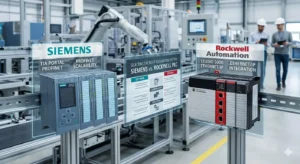
The Allen-Bradley 1769-L30ER stands as a versatile solution for modern industrial automation. This controller excels at integrating diverse hardware within a unified Ethernet architecture. In complex environments like chemical processing or bottling lines, it acts as a strategic bridge. It facilitates high-speed data exchange between Rockwell systems and third-party PLCs, such as Siemens. Moreover, its embedded dual-port Ethernet allows for direct connectivity. This eliminates the need for expensive external gateways in many localized applications. Consequently, engineers reduce system complexity and long-term maintenance costs simultaneously.

Allen-Bradley 1769-L30ER: Multi-Vendor PLC Integration Guide

EtherNet/IP and TCP/IP Communication Fundamentals

The 1769-L30ER natively supports the Common Industrial Protocol (CIP) over EtherNet/IP. However, Siemens controllers typically utilize PROFINET or the S7 protocol. To bridge this gap, engineers often implement Open User Communication (OUC) via TCP sockets. This method enables direct data transfer without secondary protocol converters. The demand for interoperable factory automation is rising globally. Therefore, choosing the correct communication interface is vital. It prevents data loss and ensures deterministic control in high-speed production environments. Proper configuration maintains the timing accuracy required for synchronized assembly tasks.

Optimizing Network Load and Deterministic Response Times

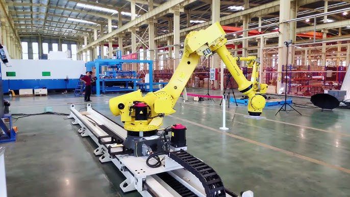
Performance in a control system depends heavily on network optimization. The L30ER supports 100 Mbps full-duplex communication on its embedded ports. Nevertheless, actual response times vary based on the Requested Packet Interval (RPI). High node counts or improper RPI settings can introduce network jitter. In addition, network topology plays a significant role in overall stability. Star topologies often provide better isolation compared to simple daisy chains. As a result, careful traffic management prevents synchronization issues in precision manufacturing processes. This is especially critical for motion-heavy applications like robotic packaging.

Enhancing Reliability through Advanced EMC Practices

Industrial environments often subject hardware to significant electrical noise and interference. The 1769-L30ER adheres to IEC 61131-2 standards for robust industrial performance. However, reliability requires strict adherence to electromagnetic compatibility (EMC) guidelines. Engineers must use shielded twisted pair (STP) cables to mitigate signal degradation. Furthermore, separating communication lines from Variable Frequency Drive (VFD) output wiring is essential. Poor shielding frequently causes intermittent communication drops during commissioning. Therefore, establishing a solid common ground point remains a foundational requirement for any stable PLC installation.

Field-Proven Installation and Maintenance Strategies

Drawing from extensive field experience at Powergear X Automation Limited, successful integration follows specific protocols. First, implement a rigorous IP addressing scheme to avoid network conflicts. Second, utilize managed industrial switches to segment broadcast traffic effectively. In high-vibration areas, such as milling or stamping, use locking RJ45 connectors. These prevent physical signal loss due to mechanical stress. Additionally, install external surge protection in environments prone to lightning or power transients. These proactive steps ensure the 1769-L30ER remains operational throughout its intended service life.

Comparative Analysis and Hardware Selection Guide

The 1769-L30ER belongs to the CompactLogix 5370 family, offering specific advantages over legacy models. While it supports many 1769-series I/O modules, firmware compatibility is paramount. It provides more memory and faster processing than the entry-level L1 series. However, it lacks the extreme node capacity of the larger L36ER controllers. When integrating with Siemens, engineers must evaluate if the built-in TCP socket capability suffices. If structured CIP data exchange is mandatory, a dedicated protocol gateway remains the industry standard. This hardware selection directly impacts both commissioning time and total system scalability.

Expert Insight from Powergear X Automation Limited

At Powergear X Automation Limited, we believe the future of industrial automation lies in open standards. The 1769-L30ER is a powerful tool because it balances proprietary performance with open connectivity. We often recommend implementing OPC UA via middleware for large-scale plant integration. This aligns with IEC 62541 standards and ensures future-proof data visibility. While direct EtherNet/IP to PROFINET communication is not native, the L30ER’s flexibility makes it a top choice for multi-vendor sites. We suggest always performing offline communication tests in Studio 5000 before live deployment.

  • Integrated Dual Ports: Supports Device Level Ring (DLR) for high network availability.
  • ⚙️ Socket Programming: Enables custom communication with non-Rockwell devices.
  • 🔧 Compact Form Factor: Saves significant cabinet space in localized control panels.
  • Standardized I/O: Compatible with a wide range of existing 1769 expansion modules.

Industrial Application Scenarios

  • Chemical Processing: Synchronizing Rockwell-based batching with Siemens-controlled safety valves.
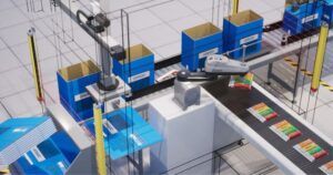
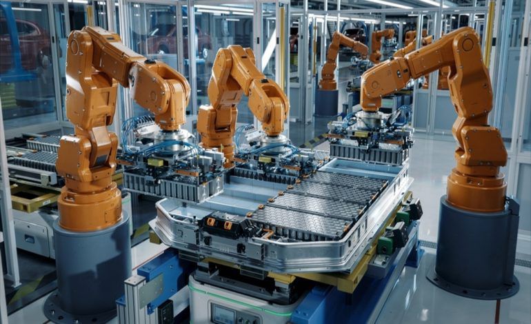
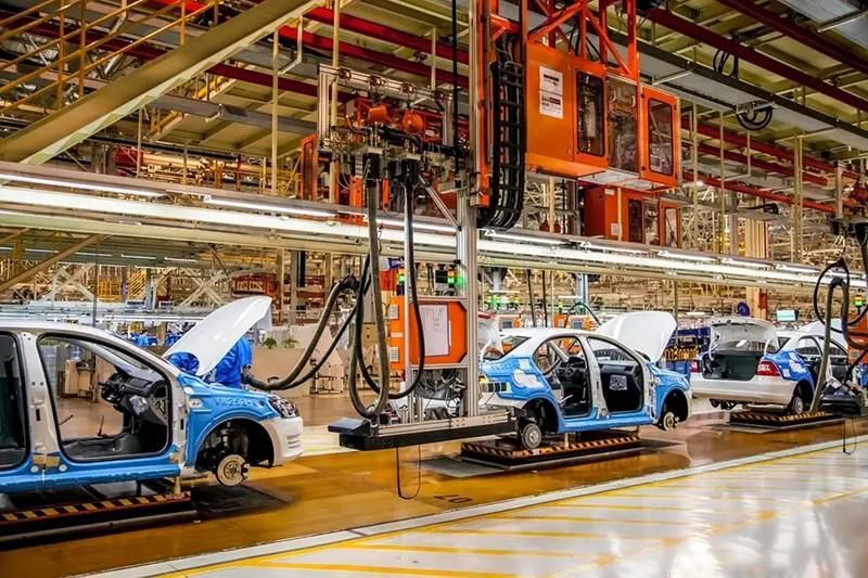
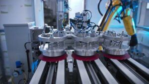
  • Automotive Assembly: Managing high-speed data flow between different robotic cells on a single backbone.
  • Water Treatment: Integrating remote pump stations with various PLC brands into a central SCADA.

Technical Frequently Asked Questions (FAQ)

Q: Does the 1769-L30ER support direct S7 protocol communication with Siemens?
No, it does not support the S7 protocol natively. You must use TCP/IP socket programming (OUC) on both ends or utilize an industrial gateway. For large-scale projects, a gateway is often the more maintainable solution as it requires less custom code.

Q: How do I resolve frequent “Connection Timeout” errors in multi-vendor setups?
This usually stems from RPI mismatches or high network broadcast traffic. From our experience, increasing the RPI slightly or moving the PLCs to a dedicated VLAN on a managed switch typically stabilizes the connection. Always check the Ethernet cable shielding near high-voltage sources first.

Q: Can I use standard commercial Ethernet cables for these connections?
We strongly advise against it. Commercial cables lack the shielding and jacket durability required for factory floors. Industrial-grade STP cables protect against EMI from motors and VFDs, which are the primary causes of intermittent packet loss in industrial control systems.

For more technical documentation or to explore high-quality automation hardware, visit the official website of Powergear X Automation Limited today.

Allen-Bradley 1769-ASCII Module: Direct Serial Integration Guide

Allen-Bradley 1769-ASCII Module: Direct Serial Integration Guide

Enhancing Industrial Traceability with the Allen-Bradley 1769-ASCII Module

Bridging Serial Devices and CompactLogix Control Systems

The Allen-Bradley 1769-ASCII module serves as a specialized gateway for integrating serial peripherals into the CompactLogix ecosystem. It allows Programmable Logic Controllers (PLCs) to interpret data from barcode scanners, weigh scales, and RFID readers directly. Consequently, manufacturers in the automotive and pharmaceutical sectors can achieve real-time traceability without expensive third-party converters. This direct integration streamlines the hardware architecture and significantly improves system responsiveness during high-speed production cycles.

Allen-Bradley 1769-ASCII Module: Direct Serial Integration Guide

Technical Architecture: Baud Rates and Buffer Management

A successful serial deployment relies heavily on precise communication parameters and data handling logic. The 1769-ASCII module supports a broad spectrum of baud rates, ranging from 9600 to 115200 bps. However, engineers must ensure the module and peripheral device share identical data bits and parity settings to prevent string corruption. Furthermore, internal buffer management plays a vital role in high-throughput environments like conveyor sorting. Proper PLC polling routines must continuously clear these buffers to avoid data overflow and missed scans.

Industrial Reliability and EMI Mitigation Strategies

Modern factory automation environments often suffer from heavy electromagnetic interference (EMI) generated by VFDs and large motors. The 1769-ASCII module incorporates built-in isolation to protect signal integrity and hardware longevity. Nevertheless, field experience suggests that shielded cabling remains a mandatory requirement for stable data acquisition. In addition, implementing a single-point grounding strategy according to IEC 60204-1 standards helps eliminate ground loops. These physical layer protections prevent the “phantom faults” that frequently plague serial communication lines.

Installation Best Practices for Harsh Environments

Commissioning serial modules requires meticulous attention to physical connectivity and mechanical stability. For instance, robotic cells and packaging machinery often subject cables to intense vibrations. Therefore, we recommend utilizing locking connectors and integrated strain relief to maintain consistent contact. Moreover, always verify the specific RS-232 or RS-485 pinout requirements of your scanner. A common oversight in the field involves neglecting the need for a null modem configuration, which can halt commissioning for hours.

Strategic Selection: ASCII Modules vs. Modern Ethernet Gateways

Deciding between the 1769-ASCII and newer Ethernet-based solutions depends on your existing infrastructure and scalability goals. While Ethernet/IP scanners offer superior diagnostics and Industry 4.0 readiness, many legacy systems still rely on robust serial protocols. According to MarketsandMarkets, the demand for bridge modules remains steady as plants extend the life of reliable legacy equipment. The 1769-ASCII is an excellent choice for point-to-point serial tasks where simplicity and cost-efficiency are the primary drivers.

Expert Insight from Powergear X Automation Limited

At Powergear X Automation Limited, we believe the 1769-ASCII remains a vital tool for localized data capture. Although the industry is shifting toward unified Ethernet architectures, serial communication still offers a “fail-safe” simplicity that complex networks sometimes lack. We advise engineers to maintain a “Gold Configuration” backup of their ASCII settings. This practice ensures that replacement modules can be deployed instantly during a failure, effectively minimizing Mean Time To Repair (MTTR).

Operational Solutions and Application Scenarios

  • Food & Beverage Batch Tracking: Real-time capture of ingredient serial numbers directly into the PLC to meet FDA compliance.
  • Automotive Part Verification: Scanning VIN barcodes at assembly stations to trigger specific robot logic via the CompactLogix backplane.
  • Warehouse Logistics: Integrating legacy weigh scales to automate parcel weight logging without PC-based middleware.

Technical Implementation Checklist

  • ✅ Match baud rate, parity, and stop bits between the PLC and the peripheral device.
  • ✅ Use high-quality shielded twisted-pair (STP) cables for RS-485 long-distance runs.
  • ✅ Implement logic-based handshaking to verify data receipt within the Studio 5000 environment.
  • ✅ Verify firmware compatibility with the CompactLogix controller before hardware installation.

Frequently Asked Questions (FAQ)

Q: Why is my 1769-ASCII module receiving garbled or incomplete strings?
This is typically caused by mismatched baud rates or electrical noise. Check your cable shielding and ensure the terminal resistor is correctly placed for RS-485 configurations. Also, confirm the ‘End of Message’ delimiter in your PLC logic matches the scanner’s output.

Q: Can this module support multiple serial devices simultaneously?
The module typically features two ports, allowing for the connection of two separate ASCII devices. However, you must configure each port independently in the I/O tree. For high-density serial needs, consider a specialized communication gateway.

Q: Does the module require separate power, or is it bus-powered?
The 1769-ASCII draws power from the CompactLogix backplane. However, you must calculate the total power consumption of your I/O bank to ensure the power supply distance rating is not exceeded, which could lead to intermittent module resets.

For more high-performance modules and expert technical support, visit the official Powergear X Automation Limited website to browse our full catalog.

Troubleshooting 1769-IR6 RTD Modules in CompactLogix Systems

Troubleshooting 1769-IR6 RTD Modules in CompactLogix Systems

Optimizing Thermal Precision with the 1769-IR6 RTD Input Module

In the demanding realm of industrial automation, temperature control serves as the backbone of process integrity. The 1769-IR6 RTD input module stands out as a premier solution for Allen-Bradley CompactLogix systems. This module provides six high-resolution channels designed to convert resistance signals from RTDs into precise digital data. Consequently, it allows engineers to monitor critical thermal variables with exceptional stability.

Troubleshooting 1769-IR6 RTD Modules in CompactLogix Systems

The Core Functionality of Resistance Temperature Detectors

The 1769-IR6 operates on the principle of resistance change in metallic elements, typically Platinum (Pt) or Nickel (Ni). As the ambient temperature fluctuates, the sensor’s electrical resistance changes in a predictable linear fashion. The module injects a small excitation current and measures the resulting voltage drop. Furthermore, it utilizes advanced onboard filtering to eliminate high-frequency interference, ensuring the PLC receives clean, actionable data for PID control loops.

Deconstructing the Overrange Protection Mechanism

An “Overrange” status on a 1769-IR6 is more than a simple error; it is a vital safety barrier. This condition triggers when the sensed resistance exceeds the defined parameters in the Studio 5000 configuration. According to industry insights from groups like IEEE, improper signal scaling remains a leading cause of process downtime. Therefore, the module flags these anomalies to prevent the controller from executing logic based on corrupted or physically impossible temperature values.

Common Triggers for Signal Faults and Overrange

Field experience suggests that hardware failure is rarely the primary culprit. Instead, most issues stem from physical installation errors or configuration mismatches. Common factors include:

  • Mismatched Sensor Profiles: Installing a Pt1000 sensor while the software remains set to Pt100 creates an immediate Overrange.
  • Wiring Discontinuity: Broken lead wires or loose terminal screws simulate infinite resistance, which the module interprets as a maximum limit breach.
  • Lead Wire Resistance: In 3-wire configurations, unbalanced resistance between leads causes significant temperature drift.
  • EMI Interference: High-voltage cables running parallel to signal lines can induce noise, pushing readings beyond the module’s threshold.

Strategic Selection: Comparing the 1769-IR6 to Alternative Modules

When selecting I/O for a CompactLogix system, engineers often weigh the 1769-IR6 against thermocouple modules like the 1769-IT6. While thermocouples handle higher temperature peaks, RTDs offer far superior accuracy and long-term stability in the -200°C to 600°C range. Additionally, the 1769-IR6 provides specific resistance-only modes. This feature is essential for custom sensing applications that do not follow standard RTD curves.

Installation Best Practices for High-Availability Environments

Maintaining a robust automation system requires a disciplined approach to field wiring. We recommend using shielded, twisted-pair cables for any run exceeding 10 meters to mitigate electromagnetic noise. Moreover, applying thread-locking compounds to screw terminals in high-vibration areas, such as near industrial compressors, prevents micro-loosening. Periodic validation using a dedicated resistance bridge or a calibrated multimeter ensures the sensor remains within its specified tolerance.

Author Insight from Powergear X Automation Limited

At Powergear X Automation Limited, we have observed a growing trend toward using Pt1000 sensors in modern plants to reduce the impact of lead-wire resistance. While the 1769-IR6 is a legacy-friendly workhorse, its performance depends entirely on the quality of the initial commissioning. We believe that investing time in precise software calibration pays dividends in reduced “nuisance trips” and extended equipment lifecycles. For more technical guides and high-quality automation components, visit Powergear X Automation Limited.

Practical Application Scenarios

  • Pharmaceutical Fermentation: Maintaining strict ±0.5°C tolerances to ensure batch consistency and regulatory compliance.
  • Food & Beverage Pasteurization: Rapidly detecting thermal deviations to prevent the distribution of unsafe products.
  • Cryogenic Storage: Monitoring ultra-low temperatures in chemical laboratories where sensor reliability is non-negotiable.

Frequently Asked Questions (FAQ)

Q1: Why does my module show Overrange even though the sensor is brand new?
This is usually caused by a configuration mismatch in Studio 5000. Ensure the selected RTD type (e.g., Pt385 or Pt3916) matches the specific coefficient of your hardware. Even a slight mismatch in the Alpha constant can trigger a fault.

Q2: How can I distinguish between a module failure and a field-side wiring issue?
Disconnect the RTD and place a known precision resistor across the module terminals. If the module reads the resistor accurately, the fault lies in your field wiring or the sensor itself. This simple loop check saves hours of diagnostic time.

Q3: Does the 1769-IR6 support 2-wire RTDs in high-precision tasks?
While supported, 2-wire setups are not recommended for precision because the module cannot compensate for lead-wire resistance. For industrial accuracy, always prefer 3-wire or 4-wire configurations to maintain signal integrity over long distances.

Fixing 1769-L33ER Flashing Red OK LED | PLC Diagnostic Guide

Fixing 1769-L33ER Flashing Red OK LED | PLC Diagnostic Guide

Troubleshooting the Flashing Red OK LED on Allen-Bradley 1769-L33ER

In the high-stakes environment of modern factory automation, the CompactLogix 1769-L33ER acts as the central intelligence for production lines. The OK status indicator provides immediate diagnostic feedback for engineers. However, a flashing red light signals a major recoverable fault that halts operations instantly. Understanding this signal is critical for industries like pharmaceuticals and chemical processing where downtime causes massive financial losses.

Fixing 1769-L33ER Flashing Red OK LED | PLC Diagnostic Guide

Identifying Major Controller Faults and System Halts

A flashing red OK LED indicates the controller has detected a major fault condition. This state typically occurs due to program corruption, invalid memory access, or hardware configuration mismatches. When the CPU enters this state, it stops executing logic to prevent unpredictable machine behavior. Consequently, motion systems freeze and I/O outputs transition to their configured safe states. From my experience at Powergear X Automation, these faults often stem from unintended array overflows in the logic.

  • Check the Major Fault Code in Studio 5000 immediately.
  • Verify that the project checksum matches the offline file.
  • Inspect the task watchdog timers for potential overlaps.
  • Ensure the user program does not contain infinite loops.

Ensuring Firmware Integrity and Non-Volatile Memory Stability

The 1769-L33ER utilizes internal non-volatile memory to safeguard critical firmware and user data. A flashing red LED often points toward a firmware mismatch or an interrupted flash process. This frequently happens if power fails during a firmware update via ControlFlash. Moreover, using a ControlLogix revision that does not align with your Studio 5000 version triggers compatibility errors. Always maintain a stable power supply during updates to avoid “bricking” the expensive CPU hardware.

Managing 1769 Backplane Communication and Module Synergy

Reliable communication between the CPU and I/O modules is the backbone of industrial control. A flashing red LED may indicate a broken connection within the 1769 backplane. Specifically, a missing or loose 1769-ECR/ECL end cap will interrupt the bus and trigger a system-wide fault. Furthermore, incompatible or poorly seated modules cause intermittent communication resets. In high-vibration packaging environments, mechanical stability is just as important as the software configuration itself.

  • Confirm the right-hand end cap is securely locked.
  • Use DIN rail end clamps to prevent module drifting.
  • Verify that all modules are compatible with the CPU revision.
  • Inspect backplane pins for signs of corrosion or bending.

Expert Maintenance Strategies to Minimize Industrial Downtime

Proactive maintenance reduces the frequency of “red light” events significantly. I recommend a structured approach: always stabilize your power with a UPS before performing maintenance. Furthermore, keep a verified backup of the .ACD project file on a secure server. In my field observations, over 60% of flashing red LED cases are resolved through software reconfiguration rather than hardware replacement. Systematic diagnosis prevents the unnecessary cost of buying new controllers when a simple reset suffices.

Practical Application Scenarios and Solutions

In a recent beverage bottling project, a 1769-L33ER displayed a flashing red OK LED during peak production. The culprit was a loose 1769-IA16 module caused by conveyor vibrations. By re-seating the module and installing rugged DIN rail clamps, we restored the line within minutes. For reliable hardware and expert technical support, visit Powergear X Automation to find high-quality automation components that keep your facility running smoothly.

Frequently Asked Questions (FAQ)

1. Can I clear a flashing red OK LED without a computer?
In some cases, toggling the physical keyswitch from RUN to PROGRAM and back to RUN can clear minor recoverable faults. However, if the light continues to flash, you must connect via Studio 5000 to identify the specific fault code before the controller will resume operation.

2. Is my 1769-L33ER permanently damaged if the LED stays red after a reboot?
Not necessarily. A flashing red light is often a “soft” failure related to firmware or logic. If the light turns solid red, that usually indicates a hardware fatality. Try performing a factory reset or re-flashing the firmware before assuming the unit is defective.

3. How do I choose between the 1769-L33ER and older 1769-L32E models?
The L33ER offers significantly more memory and faster processing speeds. When selecting hardware, ensure your existing 1769 I/O modules are supported by the newer firmware. Check the Rockwell compatibility matrix to ensure a seamless migration without unexpected major faults.

Expert Tips for Mapping HART QV with CC-PAIH51 Modules

Honeywell CC-PAIH51 Guide: Multi-Variable HART Integration

Unlocking Multi-Variable Data: A Guide to Honeywell CC-PAIH51 HART Integration

The Strategic Value of the CC-PAIH51 in Modern DCS

The Honeywell CC-PAIH51 module acts as a powerful gateway within the Experion PKS architecture. It enables seamless acquisition of multi-variable HART data from smart field instruments. In sectors like oil and gas or pharmaceuticals, transmitters often capture multiple process values simultaneously. For instance, a single device can monitor pressure, temperature, and flow. By mapping the Quaternary Variable (QV), engineers gain deeper process visibility without installing extra hardware. Consequently, this reduces wiring complexity and lowers the total cost of ownership.

Expert Tips for Mapping HART QV with CC-PAIH51 Modules

Expert Tips for Mapping HART QV with CC-PAIH51 Modules

HART Multi-Variable Support and Engineering Impact

The CC-PAIH51 supports extensive HART 5, 6, and 7 structures, including PV, SV, TV, and QV. Typically, the module retrieves the QV via HART Command 9 or Command 3. If engineers fail to map these variables correctly in the DCS, they lose critical diagnostic data. In refinery applications, this missing information could hide early warning signs of sensor drift. Therefore, proper parsing ensures that secondary measurements contribute effectively to the overall control strategy.

Understanding Scan Time and Update Rate Constraints

HART polling cycles depend on the specific channel configuration and the number of devices on the loop. Generally, secondary variable updates occur more slowly than the primary 4–20 mA analog signal. As a result, the QV is not ideal for high-speed, fast control loops. However, it remains highly valuable for asset monitoring and predictive maintenance. Misusing these variables in critical control logic can lead to sluggish system responses and operational instability.

The Importance of DD/EDD File Compatibility

Accurate interpretation of HART variables relies on matching Device Description (DD) files with the Experion library. If the DD file is outdated, the CC-PAIH51 may read raw data but fail to scale it. This often leads to “unknown parameter” errors on the operator station. Brownfield upgrades frequently encounter this specific challenge. At Powergear X Automation, we recommend verifying your DD library before any major system commissioning to avoid these common integration hurdles.

A Step-by-Step Guide to Parsing the HART QV

The CC-PAIH51 does not expose the Quaternary Variable automatically; it requires explicit configuration. Follow these technical steps for successful mapping:

  • Initialize digital communication over the 4–20 mA loop to identify the HART device.
  • Use standard HART commands to extract dynamic variables like the QV.
  • Assign the QV to a specific parameter block within the Control Builder configuration.
  • Apply correct engineering units and scaling based on the supported DD file.

Our field experience shows that QV issues often stem from missing software files rather than hardware defects. Updating the library usually restores data immediately.

Installation Standards for High Signal Integrity

Reliable HART communication requires a minimum loop resistance, typically around 250 Ohms. In large petrochemical plants with long cable runs, insufficient resistance can prevent successful QV polling. Always use shielded twisted-pair cables to protect the signal from external noise. Furthermore, ground the shields at the control cabinet end only. This practice prevents ground loops that might corrupt digital communication between the field and the DCS.

Addressing and Surge Protection in Harsh Environments

Verify that your transmitters operate in the correct HART addressing mode. Most devices should use point-to-point mode at address 0 to ensure the CC-PAIH51 recognizes all variables. Additionally, industrial environments often face lightning risks or electromagnetic interference. Installing external surge protectors compliant with IEC 61000-4 is essential for offshore platforms. Failure to protect these loops can cause intermittent loss of HART data, often misdiagnosed as module failure.

Expert Insights from Powergear X Automation

As experts at Powergear X Automation, we believe the CC-PAIH51 is more than a simple I/O module. It is a diagnostic engine that transforms basic analog loops into rich data streams. Successful integration requires a holistic approach, aligning device firmware with DCS software versions. We suggest a “pre-install audit” of your transmitter DD files to ensure a smooth startup. If you need help selecting the right Honeywell components, our team is ready to assist.

Technical Implementation Checklist

  • ✅ Verify loop resistance meets the 250 Ohm HART requirement.
  • ✅ Confirm the transmitter firmware supports HART Command 3 or 9.
  • ✅ Ensure the Experion DD library includes the latest device versions.
  • ✅ Use dedicated metallic trays to segregate signal and power cables.
  • ✅ Assign QV parameters to the correct AI channel extended blocks.

Solution Scenarios

  • Coriolis Flowmeter Monitoring: Using QV to track fluid density and temperature for mass flow accuracy.
  • Advanced Pressure Sensing: Monitoring sensor electronics temperature via QV to predict transmitter failure.
  • Asset Management: Routing diagnostic flags from field instruments directly to maintenance workstations.

Frequently Asked Questions

Q1: When is it necessary to enable QV in a HART-enabled system?
You should enable QV when using multi-variable transmitters, such as mass flowmeters or complex pressure sensors. If the device captures density, concentration, or internal diagnostics, QV provides this data without requiring additional physical I/O modules.

Q2: Can the CC-PAIH51 work with older HART 5 transmitters?
Yes, the module is backward compatible with HART 5, 6, and 7. However, the available variables depend on the device’s own capabilities. Some older HART 5 devices may only support PV and SV, so check your instrument manual before configuration.

Q3: What is the most effective way to troubleshoot missing QV data?
First, check the HART communication status in the DCS. If the primary variable is fine but QV is missing, the problem is likely a missing DD file or an unmapped parameter block. Ensure the device address is set to 0 and that the loop resistance is sufficient.

Migrating 1769-L35CR: ControlNet to EtherNet/IP Guide

Migrating 1769-L35CR: ControlNet to EtherNet/IP Guide

Optimizing Industrial Networks: The 1769-L35CR Migration from ControlNet to EtherNet/IP

The 1769-L35CR remains a cornerstone in legacy industrial automation. It successfully bridged the gap between compact hardware and powerful ControlNet capabilities. However, modern factory automation demands higher flexibility. Engineers now frequently migrate these systems to EtherNet/IP architectures. This transition resolves bandwidth bottlenecks and simplifies complex network maintenance. It also aligns older facilities with modern IIoT standards.

Migrating 1769-L35CR: ControlNet to EtherNet/IP Guide

Technical Principles of the 1769-L35CR Controller

The Allen-Bradley 1769-L35CR features an integrated ControlNet port. It utilizes the Common Industrial Protocol (CIP) for deterministic communication. This architecture ensures high-speed I/O updates and peer-to-peer interlocking. ControlNet provides scheduled bandwidth, making it highly reliable for synchronized processes. Despite its stability, the hardware is becoming rigid. It struggles to scale within data-intensive manufacturing environments. Therefore, a strategic move toward EtherNet/IP is becoming a technical necessity.

Managing Network Determinism and Throughput

ControlNet guarantees packet delivery through scheduled intervals. In contrast, EtherNet/IP relies on standard Ethernet hardware. To maintain performance, engineers must implement managed Ethernet strategies. You should utilize VLAN segmentation to isolate traffic. In addition, QoS (Quality of Service) prioritization is essential. These tools ensure that critical I/O data arrives on time. Without them, implicit traffic may suffer from jitter. This instability can disrupt motion control or batching applications.

Upgrading Communication Modules for Compatibility

Legacy ControlNet systems often use 1769-SDN or specialized interface modules. Migration requires replacing these components with Ethernet-capable hardware. Common choices include the 1769-ENBT or the higher-performance 1769-EN2T. However, many field devices do not support Ethernet natively. You must decide between replacing these devices or using protocol bridges. While gateways reduce initial costs, they often introduce latency. Direct hardware replacement usually offers better long-term reliability.

Assessing Controller Performance and CIP Limits

The 1769-L35CR has specific physical limits regarding packet processing. It possesses fewer CIP connections than modern Logix controllers. High-density I/O systems may quickly exhaust these resources. As a result, you might see increased Requested Packet Intervals (RPI). This delay directly impacts the responsiveness of your control loop. If your system requires massive expansion, consider a full upgrade. Transitioning to a newer CompactLogix 5370 or 5380 series is often more sustainable.

Strategic Installation and Maintenance Insights

Successful field migration avoids a “big bang” approach. I recommend a phased transition for critical infrastructure. First, install an EtherNet/IP backbone alongside the existing network. Gradually migrate individual remote I/O racks to the new segment. Finally, decommission the old ControlNet segments entirely. This method prevents massive commissioning delays. It also allows for easier troubleshooting of individual device conflicts.

  • Shielding: Use STP (Shielded Twisted Pair) cables to prevent EMI.
  • Switching: Only use managed industrial switches for I/O traffic.
  • Grounding: Ensure robust panel grounding to avoid intermittent dropouts.
  • Monitoring: Implement IGMP snooping to manage multicast traffic flooding.

Author’s Perspective: The Future of CIP Networks

As a specialist at Powergear X Automation, I believe the shift from ControlNet is inevitable. While ControlNet’s physical layer is robust, its proprietary nature limits data integration. EtherNet/IP provides the transparency needed for SCADA and MES systems. However, do not underestimate the complexity of network design. Ethernet is not “plug-and-play” in a deterministic environment. Proper configuration is the difference between a high-performing plant and constant downtime. For the best selection of legacy and modern modules, visit Powergear X Automation.

Common Application Scenarios

The 1769-L35CR is prevalent in diverse industries. In Oil & Gas, it manages wellhead control and remote monitoring. Pharmaceutical plants use it for precise batch processing and validation. Food & Beverage facilities rely on it for high-speed packaging lines. Migrating these sectors to Ethernet enables remote diagnostics. It also allows for easier integration with enterprise-level analytics tools.

Frequently Asked Questions (FAQ)

Q: Can I keep my 1769-L35CR and still use EtherNet/IP?
A: Yes, you can add a 1769-ENBT module to the chassis. However, the controller’s internal memory and connection limits remain the same. This may bottleneck large-scale systems.

Q: Why did my I/O start dropping after switching to an unmanaged switch?
A: Unmanaged switches cannot handle multicast traffic effectively. This leads to “broadcast storms” that overwhelm PLC ports. Always use managed switches with IGMP snooping enabled.

Q: Is the 1769-L35CR still available for new projects?
A: It is largely considered a legacy product. While still available as a replacement part, new projects should utilize the 5069 CompactLogix platform for better performance and security.

Using 1769-SDN with CompactLogix 5370: A Compatibility Guide

Using 1769-SDN with CompactLogix 5370: A Compatibility Guide

Is the Allen-Bradley 1769-SDN Scanner Compatible with CompactLogix 5370?

The 1769-SDN DeviceNet Scanner remains a critical component for bridging legacy networks with modern control systems. While the Allen-Bradley CompactLogix 5370 series natively supports 1769 I/O modules, integrating DeviceNet requires careful planning. This guide explores technical constraints, lifecycle management, and practical field insights for automation engineers.

Using 1769-SDN with CompactLogix 5370: A Compatibility Guide

The Role of 1769-SDN in Modern Industrial Automation

The 1769-SDN acts as a communication bridge between DeviceNet field devices and the CompactLogix 5370 platform. In many factory automation environments, replacing every sensor or valve manifold is cost-prohibitive. Therefore, this module allows plants to upgrade their primary controller while maintaining existing field-level assets. It effectively extends the ROI of legacy hardware during phased system migrations.

Protocol Integration Challenges and EtherNet/IP Dominance

The 5370 series controllers primarily utilize EtherNet/IP for high-speed data exchange and synchronized motion. Adding a 1769-SDN introduces a secondary protocol layer that requires specific configuration via RSNetWorx for DeviceNet. However, this extra layer can complicate system architecture. Modern control systems favor the transparency of Ethernet, making DeviceNet troubleshooting more labor-intensive for maintenance teams.

Managing I/O Data Throughput and Network Latency

DeviceNet operates at significantly lower baud rates compared to 100Mbps Ethernet standards. As a result, large networks with over 40 nodes may experience increased scan times. This latency can impact real-time responsiveness in high-speed packaging or automotive assembly lines. Engineers must prioritize critical I/O data to ensure consistent machine cycle times when using the 1769-SDN scanner.

Critical Installation and Backplane Power Requirements

Technical reliability often depends on proper hardware installation and electrical stability. The 1769-SDN draws considerable current from the 1769 bus, which can strain the system power supply. Consider these technical essentials for a stable deployment:

  • ✅ Verify the total backplane current draw before adding modules.
  • ✅ Use 121-ohm termination resistors at both trunk line ends.
  • ✅ Maintain physical separation between communication and high-voltage cables.
  • ✅ Ensure single-point grounding to prevent EMI and signal noise.
  • ✅ Monitor the module status LEDs for rapid network diagnostics.

Powergear X Automation Expert Perspective on Lifecycle Strategy

At Powergear X Automation, we view the 1769-SDN as a “transition tool” rather than a long-term solution. While it solves immediate compatibility issues, Rockwell Automation classifies DeviceNet as legacy technology. We recommend stocking spare scanners now, as component availability may tighten. Transitioning toward an all-Ethernet architecture remains the most sustainable path for future-proofing your facility.

Real-World Application Scenarios

In a recent retrofit for a chemical processing plant, the 1769-SDN allowed the client to swap an old 1769-L32E for a modern 1769-L33ER. This saved thousands in rewiring costs for existing DeviceNet instrumentation. However, for any greenfield project, we strongly advise using EtherNet/IP-based distributed I/O to take advantage of better diagnostics and faster integration.

Frequently Asked Questions

Can I configure the 1769-SDN entirely within Studio 5000?
No, you still require RSNetWorx for DeviceNet to map the scan list and set node addresses. Studio 5000 only handles the controller-to-module data tags.

What is the most common cause of “Bus-Off” errors on this module?
In our experience, nearly 80% of faults stem from physical layer issues like loose terminations or excessive drop lengths. Always check wiring before replacing hardware.

Is there a direct Ethernet replacement for DeviceNet sensors?
Most manufacturers now offer IO-Link or EtherNet/IP versions of standard sensors. If you are replacing more than 50% of your devices, skip the 1769-SDN and migrate to a modern digital protocol.

For more technical guides and high-quality automation components, visit the Powergear X Automation website to explore our extensive inventory of PLC and DCS modules.

1769-IF4I vs 1769-IF4: Isolated vs Non-Isolated Analog Modules

1769-IF4I vs 1769-IF4: Isolated vs Non-Isolated Analog Modules

Choosing Between 1769-IF4I and 1769-IF4: A Guide to Analog Signal Integrity

Understanding the Role of Isolation in Industrial PLC Systems

Modern industrial automation demands high precision and equipment longevity. The Allen-Bradley 1769-IF4I serves as a robust shield against electrical noise and ground loops. In volatile sectors like chemical processing and oil & gas, this module protects the CompactLogix backplane. It ensures measurement stability for critical process variables. However, not every project requires high-level isolation. For cost-sensitive factory automation with short cable runs, the non-isolated 1769-IF4 offers an economical alternative. Engineers must evaluate the grounding risks before selecting a non-isolated path.

1769-IF4I vs 1769-IF4: Isolated vs Non-Isolated Analog Modules

Signal Integrity and Equipment Protection Mechanisms

The fundamental distinction between these modules lies in their electrical architecture. The 1769-IF4I features channel-to-channel and backplane isolation, whereas the 1769-IF4 utilizes a shared common reference. In high-noise environments near VFD-driven motors, non-isolated modules suffer from signal drift. This interference often triggers false alarms or destabilizes PID loops. Isolation prevents fault propagation across the system. It effectively safeguards both the controller and expensive upstream instrumentation from transient voltage spikes.

Impact of Electrical Noise on Process Control Accuracy

Both modules provide 16-bit resolution, yet real-world accuracy varies significantly based on noise immunity. Electrical interference effectively reduces the resolution of non-isolated setups. In precise dosing or pharmaceutical batching, even minor fluctuations lead to material waste. We observed a 2% fluctuation in a mixing skid using non-isolated inputs. Switching to the isolated 1769-IF4I eliminated this variation immediately. This proves that hardware-based isolation outperforms software-based filtering in high-stakes environments.

Balancing Conversion Speed and Control Responsiveness

While nominal update times appear similar, system-level responsiveness tells a different story. Non-isolated modules often require heavy software filtering to stabilize readings. Consequently, this adds latency to the control loop. For fast processes like gas pressure control, these delays compromise accuracy. Isolation reduces the need for aggressive filtering. As a result, the system maintains real-time responsiveness without sacrificing signal clarity.

Critical Installation and Grounding Strategies

If you choose the 1769-IF4, you must implement a disciplined electrical design. Proper grounding prevents the “floating ground” issues that cause intermittent analog spikes. Follow these technical requirements for non-isolated installations:

  • ✅ Use single-point grounding to prevent dangerous ground loops.
  • ✅ Separate analog signal cables from high-voltage power lines.
  • ✅ Avoid routing motor or heater loads in the same conduit.
  • ✅ Install DIN-rail surge protectors for outdoor or long-distance wiring.
  • ✅ Maintain recommended spacing to manage heat and EMI.

The Powergear X Automation Perspective on Engineering Value

At Powergear X Automation, we view the 1769-IF4I as more than a module; it is an insurance policy. While the 1769-IF4 is a practical choice for localized, well-grounded systems, the cost of troubleshooting one “ghost” signal often exceeds the initial savings. We recommend the isolated version for any application involving long-distance instrumentation or high EMI. In regulated industries like pharmaceuticals, stick to isolated designs to ensure GMP compliance and simplify system validation.

For more technical insights or to source high-quality Allen-Bradley components, visit our team at Powergear X Automation. We provide the expertise and inventory to keep your plant running efficiently.

Common Application Scenarios

  • Solution A (High Risk): Use 1769-IF4I for offshore rigs or refineries where lightning and motor noise are prevalent.
  • Solution B (Cost-Effective): Use 1769-IF4 for small, standalone packaging machines with sensors located within the same cabinet.

Frequently Asked Questions (FAQ)

Q1: Can I mix isolated and non-isolated modules on the same 1769 backplane?
Yes, the CompactLogix backplane supports both simultaneously. However, ensure your field wiring keeps the isolated and non-isolated signal commons physically separated to maintain the integrity of the isolated channels.

Q2: How do I know if my environment has too much EMI for a non-isolated module?
If your cabinet houses multiple Variable Frequency Drives (VFDs) or if your analog cables run longer than 15 meters, the risk of interference is high. In these cases, the isolated 1769-IF4I is the safer engineering choice.

Q3: What is the most common failure mode when downgrading to non-isolated inputs?
The most frequent issue is “signal jumping” or erratic readings caused by ground potential differences. If your sensors are powered from different sources, a non-isolated module will likely struggle with ground loop currents.

Studio 5000 Support for 1769-L30: Compatibility & Upgrade Risks

Can the 1769-L30 Controller Still Support Studio 5000 After Upgrading?

Navigating the Shift from RSLogix 5000 to Studio 5000

Engineers often ask if the aging 1769-L30 CompactLogix can survive a software environment upgrade. Technically, the answer is yes, but this compatibility comes with significant operational caveats. Studio 5000 Logix Designer serves as the natural successor to RSLogix 5000. However, Rockwell Automation has officially designated the 1769-L30 as a discontinued legacy product. Consequently, while you can still program these units, you must operate within restrictive firmware boundaries.

The Role of 1769-L30 in Modern Industrial Automation

The 1769-L30 earned its reputation by providing reliable mid-range control for modular I/O systems. It excels in small-scale packaging lines and standalone machine control. Its deterministic performance made it a staple in various factory automation sectors for over a decade. Nevertheless, modern plants now demand higher data transparency and better cybersecurity. In these high-stakes environments, the hardware architecture of the L30 begins to show its age.

Critical Firmware and Software Lifecycle Constraints

Compatibility largely depends on the firmware version residing in your controller. Most 1769-L30 units cap out at Logix version 20.x. While Studio 5000 can open these projects, it cannot push the hardware beyond its original design. Newer software features, such as advanced motion instructions or enhanced encryption, remain inaccessible. Therefore, maintaining these systems often requires keeping older software versions active on your engineering workstations.

Managing Tight Memory and Processing Bottlenecks

With a memory capacity often hovering around 750 KB, the 1769-L30 struggles with modern code. Today’s engineers frequently integrate complex HMI tags, extensive data logging, and IIoT connectivity. These tasks consume significant memory and CPU cycles. As a result, users may experience slow scan times or even program download failures. Modernizing your hardware allows for multi-megabyte memory buffers that handle edge analytics with ease.

Best Practices for PLC Installation and Maintenance

  • Validate Your Version Matrix: Always match your Studio 5000 version exactly to the controller firmware.
  • Use Virtual Machines: Run legacy software in isolated VMs to prevent registry conflicts.
  • Check Power Distribution: Use Rockwell’s tools to calculate total current draw for modules.
  • Secure the Hardware: Utilize DIN rail end clamps to prevent module separation.
  • Inspect Side Connectors: Periodically check physical seating of 1769 modules during shutdowns.

Expert Insight from Powergear X Automation

At Powergear X Automation, we have observed that clinging to legacy hardware during a software transition creates technical debt. While the 1769-L30 is a workhorse, its lack of modern security patches makes it a vulnerability. If your facility moves toward digital transformation, hardware upgrades should coincide with your software migration. Proactive replacement prevents the inevitable emergency search for obsolete spare parts when a failure occurs.

For high-quality replacement parts and expert technical support, visit the professionals at Powergear X Automation. We specialize in sourcing hard-to-find industrial automation components.

Frequently Asked Questions (FAQ)

1. Can I upgrade a 1769-L30 project to a newer CompactLogix 5380?
Yes, Studio 5000 allows you to change the controller type in the project properties. However, you must verify I/O mapping and memory usage. The 5380 series uses different high-speed I/O modules, which may require physical wiring changes.

2. What happens if I try to load firmware version 30 or higher onto an L30?
The hardware will reject the update. The 1769-L30 architecture is physically incompatible with the enhanced binaries found in Studio 5000 v30+. You must stay at version 20 for these specific legacy controllers.

3. Is it difficult to find replacement parts for the 1769 series?
As an obsolete line, new units are increasingly rare. Most engineers now rely on refurbished stock or secondary markets. We recommend auditing your current inventory and securing critical spares before local distributors run out of stock.

Siemens vs. Rockwell PLC: Selecting the Right Automation System

Siemens vs. Rockwell PLC: Selecting the Right Automation System

Strategic Comparison: Siemens vs. Rockwell PLC Systems in Industrial Automation

The Core Value of Leading Control Systems

Siemens excels in complex scenarios requiring high system integration, such as automotive and chemical manufacturing. Its TIA Portal architecture significantly reduces cross-system debugging costs for large-scale projects. Conversely, Rockwell (Allen-Bradley) dominates the North American market and discrete manufacturing sectors. Rockwell offers a more intuitive learning path for beginners entering the PLC programming field. Therefore, Siemens provides global versatility, while Rockwell ensures rapid deployment for standardized production lines.

Siemens vs. Rockwell PLC: Selecting the Right Automation System

Programming Environments: TIA Portal vs. Studio 5000

The Siemens TIA Portal integrates PLC, HMI, and drives into a single unified platform. This integration eliminates frequent software switching and boosts overall engineering efficiency. Rockwell utilizes a modular approach with Studio 5000 and FactoryTalk separated into different packages. This separation helps beginners master individual functions but increases complexity during full system integration. Based on our field experience, Siemens allows direct variable linking, whereas Rockwell often requires manual tag configuration.

Optimizing Scan Time and System Response

Siemens S7-1200 and S7-1500 controllers maintain exceptional stability under heavy program loads. Rockwell CompactLogix systems provide highly responsive performance for smaller, high-speed applications. Precise scan times are vital for accurate motion control in packaging and robotics. However, improper task priority configuration in Rockwell systems can lead to cycle jitter. Siemens employs a default cyclic structure that is often more forgiving for less experienced programmers.

Industrial Communication Protocol Compatibility

Siemens natively supports PROFINET and Profibus, featuring mature OPC UA integration for Industry 4.0. Rockwell relies on EtherNet/IP, ensuring seamless compatibility with North American equipment ecosystems. Protocol selection dictates your future expansion costs and device hardware choices. Note that interfacing Siemens with EtherNet/IP devices usually requires an external gateway. Similarly, Rockwell systems need additional modules to communicate over PROFINET networks.

Field Installation and Maintenance Standards

Siemens hardware requires strict grounding practices, particularly for sensitive analog signal modules. Rockwell systems offer slightly higher tolerance for grounding variances under North American standards. We recommend single-point grounding to prevent circulating currents in your control cabinet. In high-vibration environments like mining, Siemens spring terminals offer superior reliability. Regular maintenance must include tightening Rockwell screw terminals to prevent intermittent I/O loss.

Powergear X Automation: Expert Engineering Perspective

At Powergear X Automation, we believe the choice depends on your regional ecosystem. Siemens offers the best flexibility for multi-brand integration in European and Asian markets. However, Rockwell remains the undisputed leader for projects based in the United States. Beyond the brand name, true engineering value lies in understanding electrical specifications and communication logic. We advise engineers to focus on mastering troubleshooting skills rather than just software syntax.

Technical Implementation Checklist

  • ✅ Match the PLC brand to the regional technical support network.
  • ✅ Use shielded twisted pair cables for all analog I/O.
  • ✅ Install external surge protection for outdoor control equipment.
  • ✅ Implement UPS backup for mission-critical automation controllers.
  • ✅ Verify communication gateway requirements for multi-protocol systems.
  • ✅ Optimize task priorities to prevent scan time fluctuations.

Strategic Industry Scenarios

  • High-Speed Packaging: Rockwell CompactLogix for intuitive motion control and local support.
  • Large Chemical Plants: Siemens S7-1500 with TIA Portal for massive system integration.
  • North American Retrofits: Allen-Bradley ControlLogix for compatibility with existing plant standards.

Frequently Asked Questions (FAQ)

Q1: Should I prioritize Siemens or Rockwell for a new international project?

Consider the project location and the local spare parts supply chain. Siemens is the better choice for Asian and European sites due to its vast ecosystem. For North American sites, Rockwell ensures easier access to technicians and replacement hardware.

Q2: Is it difficult to migrate legacy code to new PLC platforms?

Siemens provides robust migration tools for S7-300 to S7-1500 transitions. However, older Rockwell systems like SLC500 may require significant manual re-coding. Always budget extra time for I/O address mapping and communication verification during upgrades.

Q3: Which platform handles third-party device integration more efficiently?

Siemens TIA Portal generally offers better multi-vendor integration tools through standardized GSD files. Rockwell is highly efficient within its own “Premier Integration” ecosystem. For a mix of brands, Siemens typically reduces the total engineering hours required.

Back to Top
Product has been added to your cart