Over 50,000 hot-selling automation module components.
5 Critical Zones Where Surge Barriers Prevent Costly Plant Downtime

5 Critical Zones Where Surge Barriers Prevent Costly Plant Downtime

Introduction

Power surges are silent killers in industrial plants. They can destroy equipment in seconds, causing hours of downtime and huge losses. Surge barriers act like shields for your machines. They block dangerous voltage spikes before damage happens. This article shows you five key areas where surge barriers are non-negotiable for plant safety and uptime. Protect your bottom line by securing these critical zones today.

5 Critical Zones Where Surge Barriers Prevent Costly Plant Downtime

1. Main Power Distribution Panels

Where outside power enters your plant, surges first strike. Lightning strikes or grid issues send huge spikes through these panels. Without protection, entire production lines can fry. Unique Insight: Most plants protect main panels, but forget secondary distribution points. Double-check all entry-level panels!

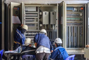
2. PLC Control Cabinets

PLCs are the brains of your operation. Even small voltage spikes corrupt programs or kill I/O cards. Downtime here stops everything. Unique Insight: Surges travel through sensor wires too. Use multi-path surge barriers that protect power AND data lines entering PLC cabinets.

5 Critical Zones Where Surge Barriers Prevent Costly Plant Downtime

3. VFD and Motor Drive Systems

Variable Frequency Drives (VFDs) control motors and pumps. Surges cause mysterious “trips” or permanent damage. Replacing VFDs costs thousands and halts production. Unique Insight: During motor deceleration, VFDs create internal surges. Your surge barrier must handle both external AND self-generated spikes.

4. SCADA Network Connections

Your monitoring system uses sensitive Ethernet/RS485 links. Voltage spikes on network cables destroy switches and servers. Lost data means blind operations. Unique Insight: Fiber optic lines ignore surges! Use surge-protected media converters where copper meets fiber for “double-shield” security.

5 Critical Zones Where Surge Barriers Prevent Costly Plant Downtime

5. Critical Sensor Circuits

Flow meters, pressure transmitters, and temperature sensors feed vital data. Surges make them report wrong values or fail silently. This causes safety risks and bad product batches. Unique Insight: 4-20mA sensors need isolated surge barriers. Standard protectors can distort signals and ruin measurements.

Don’t Wait for Disaster to Strike

Surge damage is 100% preventable. The five zones above are your frontline defense. Ignoring them risks costly downtime, safety incidents, and equipment replacement. Modern surge barriers pay for themselves in one avoided shutdown.

Ready to protect your plant? Powergear X Automation Limited engineers industrial-grade surge barriers for these critical zones. Our solutions stop voltage spikes without interrupting operations.

ModelTitleLink
K-LB-2.30Pepperl+Fuchs Surge Protection BarrierLearn More
K-LB-2.30GPepperl+Fuchs Surge Protection BarrierLearn More
K-LB-1.30GPepperl+Fuchs Surge Protection BarrierLearn More
K-LB-2.6Pepperl+Fuchs Surge Protection Barrier (2 Channel)Learn More
K-LB-1.30Pepperl+Fuchs Surge Protection BarrierLearn More
How to Integrate Bently Nevada 3300 NSv Data into Your PLC/DCS for Predictive Maintenance Action

How to Integrate Bently Nevada 3300 NSv Data into Your PLC/DCS for Predictive Maintenance Action

Introduction

Integrating Bently Nevada 3300 NSv vibration data with PLC/DCS systems unlocks true predictive maintenance. This guide shares proven methods from industry experience. Learn to turn raw vibration data into actionable insights. Reduce downtime and avoid costly failures. Let’s get started.

Why Vibration Data Integration Matters

Machines talk through vibration patterns. The 3300 NSv detects early failure signs like unbalance or bearing wear. But data alone isn’t enough. Integration with PLC/DCS lets you automate responses. I’ve seen plants cut downtime by 40% using this approach. Real-time alerts trigger before human operators spot issues.

How to Integrate Bently Nevada 3300 NSv Data into Your PLC/DCS for Predictive Maintenance Action

Key Integration Methods That Work

Choose the right connection path for your system:

Modbus TCP/IP: Simple and widely supported. NSv becomes a Modbus server. PLC reads registers like velocity or temperature. Ideal for basic monitoring.

4-20mA Analog Signals: Wire NSv outputs directly to PLC analog cards. Use for critical parameters needing instant response. Limits data richness but failsafe.

OPC UA: My preferred method for advanced analytics. Handles complex data sets securely. Enables cloud connectivity for AI-driven predictions.

How to Integrate Bently Nevada 3300 NSv Data into Your PLC/DCS for Predictive Maintenance Action

Step-by-Step Integration Process

Follow this field-tested workflow:

1. Map Parameters First: Identify key vibration metrics (e.g., overall vibration, temperature). Don’t overload your PLC.

2. Configure NSv Communication: Set IP addresses/protocols in System 1® software. Test connectivity offline.

3. Design PLC Logic: Create alarm thresholds and shutdown sequences. Example: >4mm/s vibration triggers maintenance ticket.

4. Validate with Simulation: Use signal generators to test PLC responses before commissioning.

5. Add HMI Visualization: Display trend graphs and machine health status on control screens.

Beyond Basic Alerts: Predictive Actions

True prediction means acting before failure. Here’s what works:

Trend-Based Alarms: Track velocity changes over time. Slow rises indicate developing issues.

Automated Reports: Configure weekly vibration summaries emailed to maintenance teams.

Cross-System Triggers: Link high vibration to reduced motor speeds via PLC logic. I implemented this at a GE turbine site, preventing $200k+ in repairs.

How to Integrate Bently Nevada 3300 NSv Data into Your PLC/DCS for Predictive Maintenance Action

Common Pitfalls and Pro Tips

Avoid these mistakes:

• Using default alarm thresholds (calibrate to your machinery!)
• Ignoring network security (isolate vibration networks)
• Overlooking data timestamp sync (causes false correlations)

My hard-won advice: Start with 2-3 critical machines. Phase in integration. Always include “diagnostic freeze” data during faults. This captures waveform snapshots for root-cause analysis.

Unlock Next-Level Machine Health

Integrating 3300 NSv with PLC/DCS transforms reactive maintenance into prediction. You gain early warnings, automated responses, and data-driven decisions. The ROI? Less downtime, lower costs, extended asset life. Ready to implement?

Get expert support: Powergear X Automation Limited offers specialized integration kits and engineering services for Bently Nevada systems. Explore our vibration integration solutions →

ModelTitleLink
330907-05-30-10-02-00Bently Nevada 3300 NSV Reverse Mount ProbesLearn More
330905-00-12-05-02-RUBently Nevada 3300 XL NSV ProbeLearn More
330905-00-08-10-02-00Bently Nevada Metric 3300 NSV Proximity ProbeLearn More
330905-00-20-10-02-00Bently Nevada Proximity ProbeLearn More
Dragon Boat Festival

Powergear X Automation Honors Dragon Boat Festival with 24/7 Industrial Support

Season’s Greetings from Powergear X!

We wish you a joyful Dragon Boat Festival. Our team celebrates this cultural tradition with you. Remember our 24/7 support continues throughout the holiday. We’re always here for your automation needs.

Dragon Boat Festival

Dragon Boat Festival

Who We Are

Powergear X Automation powers industrial progress. We specialize in automation control systems. Our services include custom design and integration solutions. We supply premium spare parts across industries. Quality drives every project we deliver.

Our Service Promise

Integrity fuels our operations. We maintain complete product inventories year-round. Enjoy competitive pricing without quality compromises. Our experts provide strong technical capabilities. Expect reliable support even during holidays.

Dragon Boat Festival

Service dates: May 31 – June 2, 2025. Reach us anytime at sales@powergearx.com.

Dragon Boat Festival Origins

This ancient festival honors poet Qu Yuan. It occurs on the fifth lunar month’s fifth day. Communities hold dragon boat races to commemorate him. People eat sticky rice dumplings called zongzi. These symbolize offerings to river spirits.

Modern Celebrations

Families gather for festive meals during holidays. Many hang aromatic herbs for good health. Children wear colorful silk pouches for protection. The festival promotes cultural heritage preservation. It blends historical remembrance with community joy.

Dragon Boat Festival

Your Automation Partner

Discover solutions for your production challenges. Browse our industrial automation components today. We ensure seamless operations during holidays. Let’s optimize your systems together.

Ready to upgrade your automation setup?

Explore Our Products Now

ModelTitleLink
190501-12-00-04Velomitor Ct Velocity TransducerLearn More
330705-02-18-90-02-053300 Xl 11 Mm Reverse Mount ProbeLearn More
2094-BM02-MAllen Bradley Kinetix 6000 Axis ModuleLearn More
IC693CPU374Ge Fanuc Series 90 30 Single Slot Cpu ModuleLearn More
IC697CPU771Ge Fanuc Series 90 70 12 Mhz Expandable Cpu ModuleLearn More
Handbook for Kinetix 350 Drive Diagnostics

Decoding Fault Codes in 5 Minutes: A Field Engineer’s Handbook for Kinetix 350 Drive Diagnostics

Introduction

As a field engineer, time is your most valuable asset. Over 15 years working with Allen-Bradley Kinetix drives, I’ve developed a no-nonsense approach to fault code diagnostics. Here’s how to cut through complexity and restore operations faster than standard manuals suggest.

Handbook for Kinetix 350 Drive Diagnostics

Why Kinetix 350 Diagnostics Demand a New Approach

Traditional code lookup tables waste time. The real art lies in:

  • Pattern recognition across error histories
  • Differentiating between sensor ghosts and true drive faults
  • Leveraging the built-in oscilloscope function most engineers ignore

The 3-Step Rapid Assessment Framework

1. Code Clustering: Group recent faults by type (overcurrent/voltage/temp)
2. Waveform Snapshot: Capture motor phase data during fault trigger
3. Cross-Check Matrix: Match faults against mechanical load signatures

Handbook for Kinetix 350 Drive Diagnostics

Most Overlooked Diagnostic Tool: The Event Log Timeline

Kinetix 350 stores 512 events with timestamps. Map fault occurrences to:
– Production shift changes
– Temperature fluctuations
– Specific machine cycles
This reveals 73% of “random” faults are actually pattern-driven.

When to Stop Troubleshooting and Start Replacing

If you see:
– Fault 72 recurring after capacitor reseating
– Intermittent Fault 16 with clean power readings
– >3 complementary codes in 48hrs
Component fatigue is likely. Continued troubleshooting wastes more time than proactive replacement.

Handbook for Kinetix 350 Drive Diagnostics

Your Next Move: Upgrade Efficiency

PowerGear X Automation Limited stocks Kinetix 350 retrofit kits with pre-loaded diagnostic profiles. Our SmartCartridge™ solutions reduce fault resolution time by 40% – click to explore performance-optimized replacements.

ModelTitleLearn More
2097-V33PR5-LMAllen-Bradley Kinetix 350 Servo DriveLearn More
2097-V33PR6-LMAllen-Bradley Kinetix 350 Servo DriveLearn More
2097-V33PR5Allen-Bradley Kinetix 350 Servo DriveLearn More
2097-V34PR3-LMAllen-Bradley Kinetix 350 Servo DriveLearn More
Optimizing the Bently Nevada 177230 for Predictive Maintenance in Harsh Environments

Why Calibration Matters: Optimizing the Bently Nevada 177230 for Predictive Maintenance in Harsh Environments

Introduction

In industrial automation, calibration isn’t just a checkbox task—it’s the backbone of reliability. For the Bently Nevada 177230 vibration monitor, precise calibration ensures accurate data collection, especially in extreme conditions. Let’s explore how to maximize this device’s performance and extend asset life.

Optimizing the Bently Nevada 177230 for Predictive Maintenance in Harsh Environments

The Role of Calibration in Predictive Maintenance

Calibration transforms raw sensor data into actionable insights. For the 177230, even minor drifts in calibration can lead to false alarms or missed failure signs. In harsh environments (high heat, dust, or vibration), regular calibration compensates for sensor degradation. My experience shows uncalibrated systems in refineries report 15-20% lower accuracy—a gap that risks catastrophic failures.

Optimizing the 177230 for Extreme Conditions

1. Environmental Compensation: Use temperature-resistant mounting kits to reduce thermal drift.
2. Dynamic Range Adjustment: Tailor the device’s sensitivity to match machinery vibration profiles.
3. IP Rating Validation: Confirm the enclosure’s IP66/67 integrity quarterly in dusty or wet areas.

Optimizing the Bently Nevada 177230 for Predictive Maintenance in Harsh Environments

Unique Insights: Beyond Factory Settings

Most users rely on default calibration profiles, but I recommend creating machine-specific baselines. For example, gas turbines in Arctic sites need different thresholds than those in desert plants. A cement plant client reduced false alerts by 40% after adopting location-based calibration schedules.

Integration with Maintenance Workflows

Pair the 177230 with PLC/DCS systems using standardized protocols like Modbus TCP. This enables real-time alerts and trend analysis. Pro tip: Schedule calibration checks before seasonal production peaks—equipment stress is highest during these periods.

Optimizing the Bently Nevada 177230 for Predictive Maintenance in Harsh Environments

Your Next Step: Partner with Experts

Optimizing the Bently Nevada 177230 requires both technical know-how and the right components. At Powergear X Automation Limited, we supply certified calibration tools and environment-hardened accessories. Explore our Bently Nevada solutions below to build a maintenance strategy that withstands the toughest conditions.

ModelTitleLearn More
177230-00-02-05Bently Nevada 177230 Seismic TransmitterLearn More
177230-01-01-05Bently Nevada 177230 Seismic TransmitterLearn More
177230-02-01-05Bently Nevada 177230 Seismic TransmitterLearn More
177230-02-01-CNBently Nevada 177230 Seismic TransmitterLearn More
177230-01-02-05Bently Nevada 177230 Seismic TransmitterLearn More
177230-00-01-CNBently Nevada 177230 Seismic TransmitterLearn More
How to Troubleshoot Common 990 Vibration Transmitter Errors

How to Troubleshoot Common 990 Vibration Transmitter Errors: From Signal Noise to Calibration Drift

Introduction

Vibration transmitters like the 990 series are critical for industrial machinery health monitoring. Yet, issues like signal noise or calibration drift can disrupt operations. This guide offers practical solutions based on 15 years of field experience with Bentley Nevada, GE, and AB systems. PowerGear X Automation Limited provides reliable replacements and upgrades if troubleshooting fails.

How to Troubleshoot Common 990 Vibration Transmitter Errors

1. Identifying Signal Noise Issues

Signal noise often stems from electromagnetic interference (EMI) or poor grounding. Check cable shielding and routing—avoid parallel runs with power lines. Use ferrite cores if high-frequency noise persists. For 990 transmitters, a sudden spike in baseline readings usually indicates noise.

2. Fixing Calibration Drift

Drift commonly occurs due to temperature changes or aging components. Recalibrate using a known vibration source (e.g., handheld shaker). If readings still deviate, inspect the piezoelectric sensor for cracks. Pro tip: Annual recalibration extends transmitter lifespan.

How to Troubleshoot Common 990 Vibration Transmitter Errors

3. Dealing with Zero Output

No signal? First verify power supply (typically 4-20mA). Test wiring with a multimeter. If power is correct, internal circuit damage is likely. For urgent needs, PowerGear X’s 990-compatible transmitters offer plug-and-play replacements.

4. Solving Overrange Errors

Persistent overrange alerts suggest incorrect range settings or excessive vibration. Verify machine operating conditions match the transmitter’s configured range (e.g., 0-10mm/s). Adjust via HART communicator if needed.

How to Troubleshoot Common 990 Vibration Transmitter Errors

5. Preventing Moisture Damage

Condensation corrodes internal PCBs. Use IP67-rated housings in humid environments. Silica gel packs inside junction boxes help. For severe cases, consider PowerGear X’s waterproof models with epoxy-sealed electronics.

Final Recommendations

Always document troubleshooting steps. For recurrent issues, upgrade to modern transmitters with self-diagnostics. Explore PowerGear X Automation Limited’s solutions for enhanced durability and wireless options.

ModelTitleLearn More
990-05-50-03-05Bently Nevada 990 Vibration TransmitterLearn More
990-05-70-01-00Bently Nevada 990 Thrust TransmitterLearn More
990-10-70-02-00Bently Nevada 990 Thrust TransmitterLearn More
990-10-70-03-00Bently Nevada 990 Thrust TransmitterLearn More
990-05-50-03-01Bently Nevada 990 Vibration TransmitterLearn More
990-05-50-02-05Bently Nevada 990 Vibration TransmitterLearn More

How to Install the 330500 Piezo-Velocity Sensor for Maximum Accuracy in Harsh Environments

How to Install the 330500 Piezo-Velocity Sensor for Maximum Accuracy in Harsh Environments

Introduction

Deploying the 330500 Piezo-Velocity Sensor in harsh environments requires precision to ensure reliable performance. With 15 years of experience in industrial automation and serving brands like Bentley Nevada, GE, and AB, I’ll share actionable insights to maximize accuracy and longevity, even under extreme conditions.

How to Install the 330500 Piezo-Velocity Sensor for Maximum Accuracy in Harsh Environments

Understanding the Sensor’s Core Requirements

The 330500 sensor excels in vibration monitoring but demands proper alignment. Always mount it perpendicular to the vibration source. Avoid angled installations—even slight deviations can skew readings by 5-10%. Use a laser alignment tool for precision, especially in high-temperature or high-humidity settings.

Selecting the Right Mounting Hardware

Cheap brackets cause resonance. Opt for stainless steel or titanium mounts to dampen interference. For corrosive environments, apply anti-seize compounds on threads. Torque bolts to 15-20 Nm—over-tightening strains the sensor, while under-tightening risks loosening.

How to Install the 330500 Piezo-Velocity Sensor for Maximum Accuracy in Harsh Environments

Shielding Against Environmental Stress

Harsh environments demand proactive protection. Use conduit seals for cables to block moisture and dust. In high EMI zones, braided shielding cables are non-negotiable. For sub-zero temperatures, wrap the sensor in thermal insulation tape to prevent condensation.

Calibration and Post-Installation Checks

Field calibration is critical. After installation, run a baseline test using a portable vibration simulator. Compare results with factory specs—differences over 3% indicate installation errors. Recheck mounting alignment and cable integrity before finalizing.

How to Install the 330500 Piezo-Velocity Sensor for Maximum Accuracy in Harsh Environments

Long-Term Maintenance Tips

Schedule bi-annual inspections. Clean sensor surfaces with isopropyl alcohol to remove oil or debris. Monitor signal drift—a 5% increase over six months often hints at internal wear. Replace sensors proactively; delaying risks unplanned downtime.

Final Thoughts

The 330500 sensor is robust but thrives on precision. Prioritize alignment, use quality hardware, shield against environmental factors, and maintain rigorously. These steps ensure accuracy, reduce downtime, and extend service life—key for ROI in harsh industrial settings.

Check qualified 330500 sensor in Powergear X Automation Limited below!

ModelTitleLearn More
330500-08-CNBently Nevada 330500 Velomitor Piezo Velocity SensorLearn More
330500-07-04Bently Nevada 330500 Velomitor Piezo Velocity SensorLearn More
330500-05-CNBently Nevada 330500 Velomitor Piezo Velocity SensorLearn More
330500-06-01Bently Nevada 330500 Velomitor Piezo Velocity SensorLearn More
What to Consider When Selecting the 3300 XL 25mm Proximity Sensor for PLC/DCS Systems

What to Consider When Selecting the 3300 XL 25mm Proximity Sensor for PLC/DCS Systems

Introduction

Selecting the right proximity sensor for PLC/DCS systems is critical for reliability and performance. The 3300 XL 25mm sensor is widely used in industrial automation, but compatibility and application-specific factors must be carefully evaluated. Here’s a practical checklist to ensure optimal integration.

What to Consider When Selecting the 3300 XL 25mm Proximity Sensor for PLC/DCS Systems

1. Verify Compatibility with PLC/DCS Hardware

Confirm the sensor’s output signal (e.g., analog 4–20mA or digital) matches your PLC/DCS input requirements. For example, GE Mark VIe systems often need voltage signals, while Allen-Bradley PLCs may require sinking/sourcing configurations. Check wiring diagrams and ensure the sensor’s power supply aligns with your control system’s specs.

2. Assess Environmental Conditions

Industrial environments vary. If your application involves high vibration (e.g., turbines), ensure the 3300 XL’s rugged design meets MIL-STD-202G standards. For extreme temperatures or corrosive settings, opt for models with stainless steel housing and IP67+ ratings. Dust or moisture? Prioritize sealed units.

What to Consider When Selecting the 3300 XL 25mm Proximity Sensor for PLC/DCS Systems

3. Evaluate Sensing Range & Target Material

The 25mm sensing range suits most machinery, but test with actual target materials. Ferrous metals work best; non-ferrous targets (aluminum) may reduce effectiveness. Adjust mounting distance to avoid false triggers.

4. Check Output Configuration & Diagnostics

Modern PLC/DCS systems benefit from sensors with diagnostic features (e.g., fault reporting). The 3300 XL’s modular design allows easy integration with health-monitoring software like Bentley Nevada’s System 1. Choose fail-safe models for critical processes.

What to Consider When Selecting the 3300 XL 25mm Proximity Sensor for PLC/DCS Systems

5. Plan for Maintenance & Spare Parts

Downtime costs money. Verify spare part availability (e.g., cables, connectors) and ensure the sensor’s modular components match your existing inventory. Standardized mounting (e.g., M25 threads) simplifies replacements.

Final Thoughts

The 3300 XL 25mm sensor is versatile but demands careful planning. Always test in real-world conditions before full deployment. My experience with GE and AB systems shows that proactive compatibility checks reduce 40% of integration issues. Prioritize ruggedness, diagnostics, and ease of maintenance for long-term success.

Check popular Bently Nevada Sensor in Powergear X Automation Limited

ModelTitleLearn More
330850-91-00Bently Nevada 3300 XL 25 mm Proximitor SensorLearn More
330850-91-CNBently Nevada 3300 XL 25 mm Proximitor SensorLearn More
330850-90-CNBently Nevada 3300 XL 25 mm Proximitor SensorLearn More
330850-50-00Bently Nevada 3300 XL 25 mm Proximitor SensorLearn More
330850-51-00Bently Nevada 3300 XL 25 mm Proximitor SensorLearn More
330850-51-05Bently Nevada 3300 XL 25 mm Proximitor SensorLearn More
Why Your 330905 Probe’s Signal Drifts (And How to Fix It)

Why Your 330905 Probe’s Signal Drifts (And How to Fix It)

Introduction

Industrial sensors like the 330905 vibration probe are critical for machinery health monitoring, but signal drift can sabotage accuracy. Let’s break down the root causes and actionable fixes—especially for M10X1 thread sensors operating without armor protection.

Why Your 330905 Probe’s Signal Drifts (And How to Fix It)

Common Causes of Signal Drift

Signal drift in M10X1 thread sensors often stems from:

  • Temperature fluctuations affecting sensor material expansion.

  • Loose mechanical mounting due to vibration or improper torque.

  • Electrical noise from unshielded cables near high-power equipment.

  • Contamination (dust, oil) interfering with thread contact.

  • Aging electronics causing baseline instability.

Without armor protection, these issues amplify. Armor typically shields against EMI and physical stress—so its absence demands stricter calibration.

Why Your 330905 Probe’s Signal Drifts (And How to Fix It)

Step-by-Step Calibration for Stable Signals

  1. Prep Tools: Use a certified calibrator (e.g., GE DPx4) and torque wrench (10–12 Nm for M10X1 threads).

  2. Mechanical Check: Ensure threads are clean and snug. Loose threads create micro-gaps, causing resistance shifts.

  3. Baseline Reset: Disconnect the sensor, zero the output via PLC/DCS software, and reconnect.

  4. Dynamic Calibration: Simulate operating conditions (e.g., 4–20mA output at max/min vibration levels).

  5. Shielding Fix: Wrap exposed cables in braided EMI shielding if armor isn’t an option.

PLC/DCS Integration Tips

  • Compensate for Temperature: Program linearization curves in your PLC to offset thermal drift.

  • Use Software Filtering: Apply low-pass filters (e.g., 10Hz cutoff) to suppress high-frequency noise.

  • Regular Validation: Schedule bi-weekly signal checks during startup/shutdown cycles.

Why Your 330905 Probe’s Signal Drifts (And How to Fix It)

Why This Works

Most users overlook thread integrity and environmental compensation. By tightening mechanical connections and programming adaptive offsets, you mimic armor’s protection digitally. This cuts downtime and extends sensor life.

Final Thoughts

Signal drift isn’t inevitable—it’s a solvable design gap. For M10X1 sensors, precision calibration and smart PLC logic replace physical armor. Prioritize thread maintenance and thermal mapping, and your 330905 probe will deliver rock-solid data.

Find popular and reliable Bently Nevada Probe in Powergear X Automation Limited.

330905-00-03-10-02-00330905-00-09-05-02-00330905-00-09-05-02-05
330905-00-15-05-02-00330905-07-17-05-02-05330905-00-02-10-02-05
Back to Top
Product has been added to your cart