Over 50,000 hot-selling automation module components.
How to Optimize Your PLC Code for Maximum Performance and Reliability

Boosting Efficiency: How to Optimize Your PLC Code for Maximum Performance and Reliability

Introduction

Hello, fellow automation enthusiasts! I’m here to share some practical advice on a topic that’s critical to our work: writing efficient and reliable PLC code. As someone who’s spent years in the field, I know that good code doesn’t just work—it works well. It’s clean, easy to maintain, and performs flawlessly under pressure. In this guide, I’ll walk you through some key strategies to get the most out of your PLC systems, sharing a few unique insights I’ve picked up along the way.

How to Optimize Your PLC Code for Maximum Performance and Reliability

1. Simplify Your Logic: The “KISS” Principle

The “Keep It Simple, Stupid” (KISS) principle is a golden rule in PLC programming. Complex code is hard to troubleshoot and slow to execute. My advice? Break down complex processes into smaller, manageable subroutines or functions. Use simple, direct logic wherever possible. Instead of a single, sprawling routine with hundreds of rungs, create multiple, well-named routines for specific tasks like “Motor Control,” “Safety Interlocks,” or “HMI Communication.” This makes your code more readable and your system easier to debug.

2. Optimize Data Handling: Efficient Memory Management

Memory isn’t infinite, and how you use it directly impacts performance. One common mistake is using a mix of data types when a single type would suffice. For example, if you’re working with a set of boolean values, don’t use 16 separate INT variables. Use a single DINT or DWORD and manage the individual bits. This reduces memory usage and speeds up data access. Another tip: use structured text (ST) for mathematical calculations. It’s often more efficient and easier to read than a long chain of ladder logic rungs for complex math.

How to Optimize Your PLC Code for Maximum Performance and Reliability

3. Prioritize Your Scan Time: The Key to Reliability

The PLC scan time is the loop that executes your program. A long scan time can lead to missed events and system instability. To keep it short and consistent, avoid using a single, large program file. Use function blocks and subroutines to organize your code and, most importantly, execute code only when it’s needed. For example, use a trigger or a flag to call a complex diagnostic routine only after a fault has occurred, not on every scan. Also, be mindful of using indirect addressing or complex loops within your main scan, as these can add significant, unpredictable delays.

4. Unique Insight: Don’t Just Write Code, Write “Future-Proof” Code

This is my personal philosophy: write code for the next person who has to work on it, and that person might be you in five years. This means adding clear comments, using descriptive tag names (e.g., Motor1_Run_CMD instead of M1_R_C), and creating a consistent coding standard. My unique take is to document not just what the code does, but also why it does it. Explain the design choices and the logic behind them. This “why” documentation is invaluable for troubleshooting and modifications down the road, and it’s a practice many people overlook.

In Conclusion: The Path to Better Automation

Writing great PLC code is a skill that develops with experience and a commitment to best practices. By simplifying logic, optimizing data, managing scan time, and embracing a “future-proof” mindset, you can create systems that are not only efficient and reliable but also a pleasure to work with.

Ready to take your automation projects to the next level? Explore the robust and innovative solutions from Powergear X Automation Limited.

👉 Click here to check out our latest products and see how our hardware can complement your expertly crafted code!

Maximizing Performance with Allen-Bradley Kinetix 300

Maximizing Performance with Allen-Bradley Kinetix 300: A Step-by-Step Setup Guide

Introduction

The Foundation: Hardware and Software Setup

Before we do anything, let’s get the basics right. A good start makes everything else easy.

Mounting and Wiring

This might sound simple, but it’s crucial. Ensure the drive is mounted in a cabinet with proper airflow. Heat is the enemy of electronics. When wiring, pay close attention to the manual. I’ve seen countless hours wasted because of a simple wiring mistake. Make sure your power, motor, and feedback cables are correctly terminated and shielded to prevent electrical noise.

Maximizing Performance with Allen-Bradley Kinetix 300

Software Installation

You’ll need the Studio 5000 Logix Designer and DriveTools SP. Make sure you have the latest versions. Compatibility issues between software and firmware are a common headache. My tip? Always check the Rockwell Automation Product Compatibility and Download Center (PCDC) before you start. It saves so much time later.

Getting Connected and Configuring the Drive

Now that the physical setup is done, let’s talk about the digital side. This is where the magic happens.

Establishing Communication

Connect your PC to the Kinetix 300 via an Ethernet cable. Open Studio 5000 and add the drive to your project’s I/O configuration. The Kinetix 300 uses EtherNet/IP, which makes this part very straightforward. Make sure your IP addresses are set up correctly. A unique IP for each device is a must.

Drive Configuration

Once connected, open DriveTools SP. Here’s where you input all your motor and application data. Don’t guess here. Use the motor’s nameplate data. The Kinetix 300 has a powerful auto-tuning feature, but it works best with accurate information. My unique insight? I’ve found that manually inputting the motor’s inertia can sometimes give you a better starting point than letting the software guess.

The Power of Tuning and Optimization

This is the most important step for maximizing performance. A poorly tuned drive can lead to shaky motion, overshoot, and instability.

The Auto-Tune Feature

The Kinetix 300’s auto-tune is an excellent starting point. It calculates the basic PID (Proportional, Integral, Derivative) values for your system. Run this feature with the motor disconnected from the load first, if possible. This gives a clean, accurate baseline.

Manual Tuning (Pro Tip)

After auto-tuning, you often need to fine-tune the system. I always start with the Proportional Gain (Kp). Increase it slowly until you see the motor start to oscillate, then back off a bit. Next, add some Integral Gain (Ki) to eliminate any steady-state error. Finally, use a small amount of Derivative Gain (Kd) to dampen any overshoot. My secret? Use the Trend tool in Studio 5000 to visualize the motion profile. It’s the best way to see what’s happening and make precise adjustments.

Conclusion: Achieving Peak Performance

By following these steps, you’ll go from a basic setup to a high-performance system. The Allen-Bradley Kinetix 300 is a robust and capable drive. The key to unlocking its full potential is a careful, systematic approach. Getting the hardware and software basics right, configuring the drive accurately, and taking the time to fine-tune your application will result in smooth, precise, and reliable motion.

Remember, a well-tuned system is a happy system. It reduces wear and tear, increases efficiency, and makes your machine more productive.

Ready to start your next project? We have the Allen-Bradley Kinetix 300 and all the necessary accessories you need.

Click here to explore our full range of Allen-Bradley Kinetix products at Powergear X Automation Limited!

Step-by-Step Setup Guide for Allen-Bradley PowerFlex 40P AC Drives in Industrial Automation

Step-by-Step Setup Guide for Allen-Bradley PowerFlex 40P AC Drives in Industrial Automation

Welcome, fellow engineers! This practical guide walks you through setting up Allen-Bradley PowerFlex 40P AC Drives, sharing hands-on insights for efficient commissioning in industrial systems.

Understanding the PowerFlex 40P: My Perspective

The PowerFlex 40P delivers exceptional balance between features and simplicity. Its sensorless vector control and compact design make it ideal for applications requiring precise speed control without encoder feedback, especially where panel space is limited.

Essential Pre-Installation Checks

Critical preparations before wiring:

  • Power Verification: Confirm voltage/current ratings match supply – check nameplate to prevent damage
  • Environment: Ensure clean, dry, cool location – avoid dust, moisture and excessive heat
  • Motor Compatibility: Verify motor HP, voltage, and current ratings match drive capabilities

Wiring the PowerFlex 40P: Practical Tips

Power Wiring (L1/L2/L3 to T1/T2/T3):
Use oversized wires for better current handling and heat dissipation. Connect AC power to L terminals and motor to T terminals.

Control Wiring:

  • Separate control wires from power cables to prevent noise interference
  • Always use shielded cables for analog signals

Grounding Protocol:
Connect ground terminal directly to earth ground – critical for safety and noise reduction.

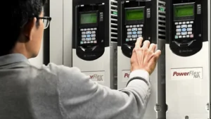
Allen-Bradley PowerFlex 40P Frequency Drive

Basic Configuration and Parameter Setup

Initial Power-Up:
After securing connections, apply power – keypad should illuminate.

Motor Data Entry:
Set these parameters precisely from motor nameplate:

  • P031 [Motor NP Volts]
  • P033 [Motor NP Amps]
  • P034 [Motor NP Freq]
  • P035 [Motor NP RPM]

Control Source Selection:
Configure A041 [Start Source A] for keypad (initial testing), digital inputs (PLC), or analog input.

Speed Reference Scaling:
For analog inputs:

  • Set P038 [Analog Input 1 Sel]
  • Scale with A051 [Anlg In1 Scale Lo] and A052 [Anlg In1 Scale Hi]

Advanced Considerations and Troubleshooting

Auto-Tune Optimization:
Execute P040 [Motor Auto Tune] to measure motor characteristics for peak performance.

Acceleration/Deceleration:
Balance P044 [Accell Time 1] and P045 [Decel Time 1] to avoid trips or sluggish operation.

Fault Management:
Interpret common codes – address root causes of overcurrent, overvoltage, and ground faults.

Preventive Maintenance:

  • Keep cooling fins dust-free
  • Regularly check terminal tightness

Conclusion: Empowering Your Industrial Automation

Mastering PowerFlex 40P setup requires attention to wiring detail, accurate parameter entry, and proactive troubleshooting – essential skills for robust automation systems.

Ready to upgrade your industrial control systems? Click here to explore Allen-Bradley PowerFlex 40P AC Drives and automation solutions from Powergear X Automation Limited.

Back to Top
Product has been added to your cart