1769-PA2 Placement Guide: CompactLogix Power Supply Tips
Optimizing 1769-PA2 Power Supply Placement for CompactLogix Reliability
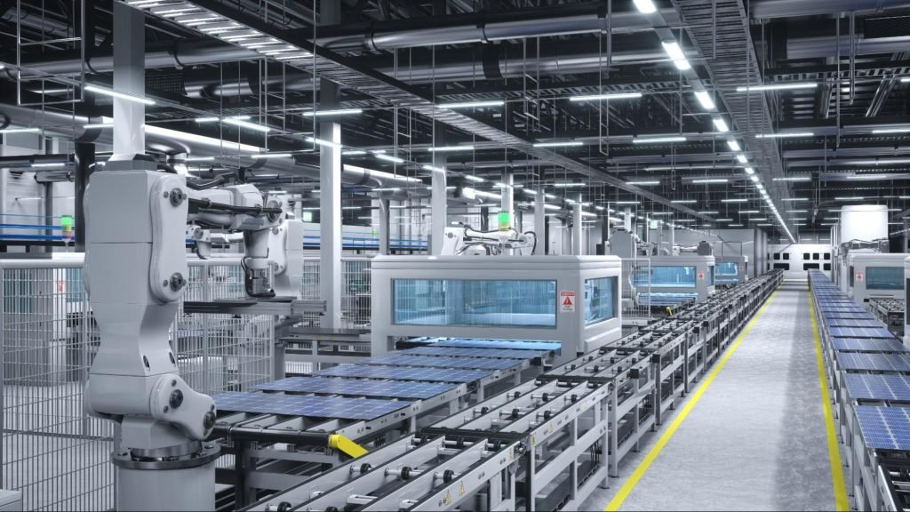
Field engineers often overlook the critical role of hardware positioning during PLC commissioning. In high-stakes environments like pharmaceutical clean rooms and chemical plants, a misplaced power supply leads to intermittent faults. The 1769-PA2 serves as the backbone of the CompactLogix local I/O system. Correct installation ensures long-term stability and minimizes costly production downtime.
Maximizing Industrial Control System Performance
The 1769-PA2 provides essential AC power to the 1769 bus, supporting both the controller and I/O modules. In industrial automation, power distribution must be deterministic to prevent communication errors. This module converts 120/240V AC input into steady backplane voltage. Consequently, its physical location determines how effectively power reaches every downstream component in the rack.
Critical Rules for Backplane Power Distribution
In the CompactLogix architecture, electrical current flows strictly from left to right across the bus. If you place the 1769-PA2 incorrectly, end-of-cap modules may suffer from significant voltage drops. As a result, users frequently report random I/O dropouts or non-recoverable hardware faults. Our team at Powergear X Automation recommends verifying the power budget for every expansion bank to ensure peak efficiency.
Thermal Management in High-Density Enclosures
The 1769-PA2 is a linear power supply that radiates heat during continuous operation. Excess heat often migrates to adjacent modules, affecting sensitive analog or motion control cards. Therefore, maintaining proper spacing is vital in 24/7 manufacturing facilities. We suggest placing a standard digital I/O module between the power supply and high-precision analog hardware to act as a thermal buffer.
Ensuring Electrical Safety and Surge Protection
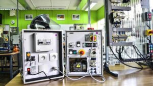
Standard 1769-PA2 units lack integrated heavy-duty surge suppression. In factory environments with unstable mains power, voltage spikes can damage the internal circuitry of the PLC. Moreover, loose wiring terminals remain a leading cause of unexpected system resets. Always use a dedicated protective earth (PE) connection rather than relying on the DIN rail for grounding.
Technical Installation Highlights
- ✅ Mount the 1769-PA2 at the far left of the local I/O assembly.
- ✅ Ensure all controllers and I/O modules sit to the right of the supply.
- ✅ Torque all AC terminal screws to the manufacturer’s specific torque ratings.
- ✅ Clean ventilation slots annually to prevent dust buildup and overheating.
- ✅ Use thermal imaging during full-load testing to identify potential hot spots.
- ✅ Verify the input voltage selector switch matches your local power source.
B2B Solutions and Field Insights
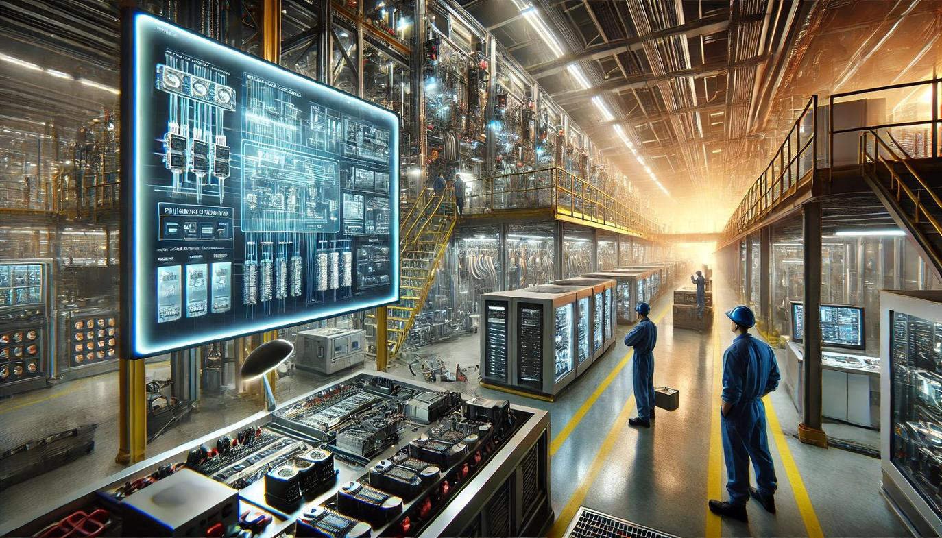
At Powergear X Automation, we see that technical success depends on following Rockwell Automation standards. While many engineers focus on software logic, physical layer stability is equally important. Investing time in correct hardware orientation reduces future maintenance costs. For high-demand applications, always choose genuine components to ensure compatibility with 1769-series hardware.
Looking for reliable hardware or expert technical guidance? Explore the full range of Allen-Bradley solutions at Powergear X Automation to secure your facility’s future.
Expert FAQ: Common Implementation Challenges
Can I use one 1769-PA2 to power two separate I/O banks?
No, this is a common misconception. Each 1769-PA2 is designed to support only one local I/O group. Expansion banks require their own dedicated power modules to maintain bus integrity. Attempting to “daisy-chain” power across banks violates IEC safety standards and will cause system instability.
How does the 1769-PA2 handle aging in pharmaceutical environments?
Chemical and pharmaceutical plants often have strict climate controls, but internal cabinet temperatures can still rise. We have observed that PA2 modules running near 100% capacity age significantly faster. Our advice is to design your system so the power supply operates at 70-80% of its rated maximum current.
What should I check first if my PLC resets during motor starts?
First, inspect the AC input of your 1769-PA2. Large motors often cause brownouts or EMI on the shared power line. In these cases, installing an isolation transformer or a dedicated UPS for the PLC rack is the best way to ensure continuous operation without logic resets.
Application Scenarios
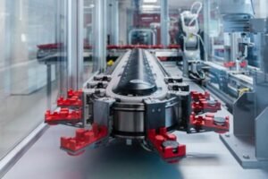
- Automotive Assembly: Ensuring high-speed I/O response by minimizing bus voltage ripple.
- Water Treatment: Providing stable power for long-distance remote I/O configurations.
- Food and Beverage: Protecting control logic from power fluctuations during heavy machinery cycles.