Over 50,000 hot-selling automation module components.
Shop Categories
How to Troubleshoot Common 990 Vibration Transmitter Errors

How to Troubleshoot Common 990 Vibration Transmitter Errors: From Signal Noise to Calibration Drift

Introduction

Vibration transmitters like the 990 series are critical for industrial machinery health monitoring. Yet, issues like signal noise or calibration drift can disrupt operations. This guide offers practical solutions based on 15 years of field experience with Bentley Nevada, GE, and AB systems. PowerGear X Automation Limited provides reliable replacements and upgrades if troubleshooting fails.

How to Troubleshoot Common 990 Vibration Transmitter Errors

1. Identifying Signal Noise Issues

Signal noise often stems from electromagnetic interference (EMI) or poor grounding. Check cable shielding and routing—avoid parallel runs with power lines. Use ferrite cores if high-frequency noise persists. For 990 transmitters, a sudden spike in baseline readings usually indicates noise.

2. Fixing Calibration Drift

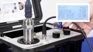
Drift commonly occurs due to temperature changes or aging components. Recalibrate using a known vibration source (e.g., handheld shaker). If readings still deviate, inspect the piezoelectric sensor for cracks. Pro tip: Annual recalibration extends transmitter lifespan.

How to Troubleshoot Common 990 Vibration Transmitter Errors

3. Dealing with Zero Output

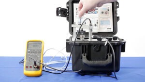
No signal? First verify power supply (typically 4-20mA). Test wiring with a multimeter. If power is correct, internal circuit damage is likely. For urgent needs, PowerGear X’s 990-compatible transmitters offer plug-and-play replacements.

4. Solving Overrange Errors

Persistent overrange alerts suggest incorrect range settings or excessive vibration. Verify machine operating conditions match the transmitter’s configured range (e.g., 0-10mm/s). Adjust via HART communicator if needed.

How to Troubleshoot Common 990 Vibration Transmitter Errors

5. Preventing Moisture Damage

Condensation corrodes internal PCBs. Use IP67-rated housings in humid environments. Silica gel packs inside junction boxes help. For severe cases, consider PowerGear X’s waterproof models with epoxy-sealed electronics.

Final Recommendations

Always document troubleshooting steps. For recurrent issues, upgrade to modern transmitters with self-diagnostics. Explore PowerGear X Automation Limited’s solutions for enhanced durability and wireless options.

Model Title Learn More
990-05-50-03-05 Bently Nevada 990 Vibration Transmitter Learn More
990-05-70-01-00 Bently Nevada 990 Thrust Transmitter Learn More
990-10-70-02-00 Bently Nevada 990 Thrust Transmitter Learn More
990-10-70-03-00 Bently Nevada 990 Thrust Transmitter Learn More
990-05-50-03-01 Bently Nevada 990 Vibration Transmitter Learn More
990-05-50-02-05 Bently Nevada 990 Vibration Transmitter Learn More

How to Install the 330500 Piezo-Velocity Sensor for Maximum Accuracy in Harsh Environments

How to Install the 330500 Piezo-Velocity Sensor for Maximum Accuracy in Harsh Environments

Introduction

Deploying the 330500 Piezo-Velocity Sensor in harsh environments requires precision to ensure reliable performance. With 15 years of experience in industrial automation and serving brands like Bentley Nevada, GE, and AB, I’ll share actionable insights to maximize accuracy and longevity, even under extreme conditions.

How to Install the 330500 Piezo-Velocity Sensor for Maximum Accuracy in Harsh Environments

Understanding the Sensor’s Core Requirements

The 330500 sensor excels in vibration monitoring but demands proper alignment. Always mount it perpendicular to the vibration source. Avoid angled installations—even slight deviations can skew readings by 5-10%. Use a laser alignment tool for precision, especially in high-temperature or high-humidity settings.

Selecting the Right Mounting Hardware

Cheap brackets cause resonance. Opt for stainless steel or titanium mounts to dampen interference. For corrosive environments, apply anti-seize compounds on threads. Torque bolts to 15-20 Nm—over-tightening strains the sensor, while under-tightening risks loosening.

How to Install the 330500 Piezo-Velocity Sensor for Maximum Accuracy in Harsh Environments

Shielding Against Environmental Stress

Harsh environments demand proactive protection. Use conduit seals for cables to block moisture and dust. In high EMI zones, braided shielding cables are non-negotiable. For sub-zero temperatures, wrap the sensor in thermal insulation tape to prevent condensation.

Calibration and Post-Installation Checks

Field calibration is critical. After installation, run a baseline test using a portable vibration simulator. Compare results with factory specs—differences over 3% indicate installation errors. Recheck mounting alignment and cable integrity before finalizing.

How to Install the 330500 Piezo-Velocity Sensor for Maximum Accuracy in Harsh Environments

Long-Term Maintenance Tips

Schedule bi-annual inspections. Clean sensor surfaces with isopropyl alcohol to remove oil or debris. Monitor signal drift—a 5% increase over six months often hints at internal wear. Replace sensors proactively; delaying risks unplanned downtime.

Final Thoughts

The 330500 sensor is robust but thrives on precision. Prioritize alignment, use quality hardware, shield against environmental factors, and maintain rigorously. These steps ensure accuracy, reduce downtime, and extend service life—key for ROI in harsh industrial settings.

Check qualified 330500 sensor in Powergear X Automation Limited below!

Model Title Learn More
330500-08-CN Bently Nevada 330500 Velomitor Piezo Velocity Sensor Learn More
330500-07-04 Bently Nevada 330500 Velomitor Piezo Velocity Sensor Learn More
330500-05-CN Bently Nevada 330500 Velomitor Piezo Velocity Sensor Learn More
330500-06-01 Bently Nevada 330500 Velomitor Piezo Velocity Sensor Learn More
What to Consider When Selecting the 3300 XL 25mm Proximity Sensor for PLC/DCS Systems

What to Consider When Selecting the 3300 XL 25mm Proximity Sensor for PLC/DCS Systems

Introduction

Selecting the right proximity sensor for PLC/DCS systems is critical for reliability and performance. The 3300 XL 25mm sensor is widely used in industrial automation, but compatibility and application-specific factors must be carefully evaluated. Here’s a practical checklist to ensure optimal integration.

What to Consider When Selecting the 3300 XL 25mm Proximity Sensor for PLC/DCS Systems

1. Verify Compatibility with PLC/DCS Hardware

Confirm the sensor’s output signal (e.g., analog 4–20mA or digital) matches your PLC/DCS input requirements. For example, GE Mark VIe systems often need voltage signals, while Allen-Bradley PLCs may require sinking/sourcing configurations. Check wiring diagrams and ensure the sensor’s power supply aligns with your control system’s specs.

2. Assess Environmental Conditions

Industrial environments vary. If your application involves high vibration (e.g., turbines), ensure the 3300 XL’s rugged design meets MIL-STD-202G standards. For extreme temperatures or corrosive settings, opt for models with stainless steel housing and IP67+ ratings. Dust or moisture? Prioritize sealed units.

What to Consider When Selecting the 3300 XL 25mm Proximity Sensor for PLC/DCS Systems

3. Evaluate Sensing Range & Target Material

The 25mm sensing range suits most machinery, but test with actual target materials. Ferrous metals work best; non-ferrous targets (aluminum) may reduce effectiveness. Adjust mounting distance to avoid false triggers.

4. Check Output Configuration & Diagnostics

Modern PLC/DCS systems benefit from sensors with diagnostic features (e.g., fault reporting). The 3300 XL’s modular design allows easy integration with health-monitoring software like Bentley Nevada’s System 1. Choose fail-safe models for critical processes.

What to Consider When Selecting the 3300 XL 25mm Proximity Sensor for PLC/DCS Systems

5. Plan for Maintenance & Spare Parts

Downtime costs money. Verify spare part availability (e.g., cables, connectors) and ensure the sensor’s modular components match your existing inventory. Standardized mounting (e.g., M25 threads) simplifies replacements.

Final Thoughts

The 3300 XL 25mm sensor is versatile but demands careful planning. Always test in real-world conditions before full deployment. My experience with GE and AB systems shows that proactive compatibility checks reduce 40% of integration issues. Prioritize ruggedness, diagnostics, and ease of maintenance for long-term success.

Check popular Bently Nevada Sensor in Powergear X Automation Limited

Model Title Learn More
330850-91-00 Bently Nevada 3300 XL 25 mm Proximitor Sensor Learn More
330850-91-CN Bently Nevada 3300 XL 25 mm Proximitor Sensor Learn More
330850-90-CN Bently Nevada 3300 XL 25 mm Proximitor Sensor Learn More
330850-50-00 Bently Nevada 3300 XL 25 mm Proximitor Sensor Learn More
330850-51-00 Bently Nevada 3300 XL 25 mm Proximitor Sensor Learn More
330850-51-05 Bently Nevada 3300 XL 25 mm Proximitor Sensor Learn More
Why Your 330905 Probe’s Signal Drifts (And How to Fix It)

Why Your 330905 Probe’s Signal Drifts (And How to Fix It)

Introduction

Industrial sensors like the 330905 vibration probe are critical for machinery health monitoring, but signal drift can sabotage accuracy. Let’s break down the root causes and actionable fixes—especially for M10X1 thread sensors operating without armor protection.

Why Your 330905 Probe’s Signal Drifts (And How to Fix It)

Common Causes of Signal Drift

Signal drift in M10X1 thread sensors often stems from:

  • Temperature fluctuations affecting sensor material expansion.

  • Loose mechanical mounting due to vibration or improper torque.

  • Electrical noise from unshielded cables near high-power equipment.

  • Contamination (dust, oil) interfering with thread contact.

  • Aging electronics causing baseline instability.

Without armor protection, these issues amplify. Armor typically shields against EMI and physical stress—so its absence demands stricter calibration.

Why Your 330905 Probe’s Signal Drifts (And How to Fix It)

Step-by-Step Calibration for Stable Signals

  1. Prep Tools: Use a certified calibrator (e.g., GE DPx4) and torque wrench (10–12 Nm for M10X1 threads).

  2. Mechanical Check: Ensure threads are clean and snug. Loose threads create micro-gaps, causing resistance shifts.

  3. Baseline Reset: Disconnect the sensor, zero the output via PLC/DCS software, and reconnect.

  4. Dynamic Calibration: Simulate operating conditions (e.g., 4–20mA output at max/min vibration levels).

  5. Shielding Fix: Wrap exposed cables in braided EMI shielding if armor isn’t an option.

PLC/DCS Integration Tips

  • Compensate for Temperature: Program linearization curves in your PLC to offset thermal drift.

  • Use Software Filtering: Apply low-pass filters (e.g., 10Hz cutoff) to suppress high-frequency noise.

  • Regular Validation: Schedule bi-weekly signal checks during startup/shutdown cycles.

Why Your 330905 Probe’s Signal Drifts (And How to Fix It)

Why This Works

Most users overlook thread integrity and environmental compensation. By tightening mechanical connections and programming adaptive offsets, you mimic armor’s protection digitally. This cuts downtime and extends sensor life.

Final Thoughts

Signal drift isn’t inevitable—it’s a solvable design gap. For M10X1 sensors, precision calibration and smart PLC logic replace physical armor. Prioritize thread maintenance and thermal mapping, and your 330905 probe will deliver rock-solid data.

Find popular and reliable Bently Nevada Probe in Powergear X Automation Limited.

330905-00-03-10-02-00 330905-00-09-05-02-00 330905-00-09-05-02-05
330905-00-15-05-02-00 330905-07-17-05-02-05 330905-00-02-10-02-05
3300 NSv probes

How to Choose the Optimal 3300 NSv Probe Variant for PLC & DCS Systems

Choosing the right 3300 NSv probe for PLC/DCS systems hinges on thread compatibility (NPT, BSP), armor durability, and environmental resilience. Verify thread types to prevent leaks or unstable readings. Select armor materials (stainless steel, chemical-resistant coatings) based on physical or chemical risks. Prioritize IP/NEMA ratings for moisture, dust, or temperature extremes. Align electrical outputs (4-20 mA, HART) with control system requirements. Proper installation and routine maintenance ensure long-term accuracy. Addressing these factors optimizes performance and reduces downtime.

Industrial Automation Trends 2025

Top 7 Industrial Automation Trends Shaping Control Modules in 2025

The industrial automation landscape is evolving rapidly, driven by advancements in AI, IoT, and sustainable practices. For engineers and decision-makers in control systems, staying updated on emerging trends is critical to maintaining competitiveness. Here are the top 7 industrial automation trends for 2025 that will redefine industrial control modules:

Industrial Automation Trends 2025

1. AI-Powered Predictive Maintenance

AI algorithms will dominate automation control modules, enabling real-time anomaly detection and predictive maintenance. Systems will self-optimize, reducing downtime by up to 30% and extending equipment lifespan.

2. Edge Computing Integration

Decentralized processing via edge computing minimizes latency for mission-critical operations. Expect control modules to prioritize local data analysis, ensuring faster response times in IIoT environments.

3. Digital Twin Expansion

Digital twins will become standard for simulating control module performance. Manufacturers can test upgrades virtually, cutting deployment risks and costs by 25%.

4. Cybersecurity-First Design

With rising connectivity, embedded security protocols in control modules (e.g., zero-trust architectures) will protect against sophisticated cyber threats.

5. Sustainable Automation Practices

Energy-efficient control modules powered by renewable energy algorithms will align with global net-zero goals, reducing carbon footprints without sacrificing productivity.

6. 5G-Enabled Wireless Control

Ultra-reliable 5G networks will support wireless control modules, enabling flexible factory layouts and remote system adjustments.

7. Human-Machine Collaboration

Advanced HMIs (Human-Machine Interfaces) with voice/gesture controls will simplify interactions, boosting operator efficiency in complex environments.

Why This Matters for Your Business
Adopting these trends ensures your automation systems remain agile, secure, and cost-effective. Start by auditing legacy control modules, piloting AI-driven tools, and partnering with vendors offering future-proof solutions.

Final Thoughts
2025 will prioritize smarter, greener, and interconnected automation systems. By embracing these trends early, industrial players can unlock productivity gains and long-term resilience.

Back to Top
Skype
Email
Phone
WhatsApp
WhatsApp
Phone
Email
Skype
Product has been added to your cart