



Product details
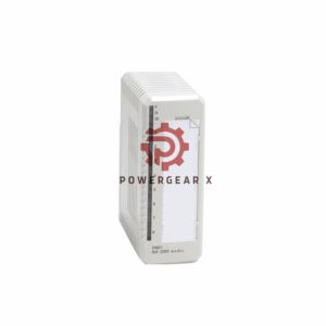
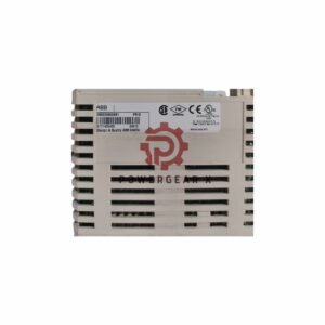
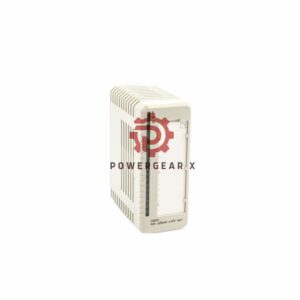
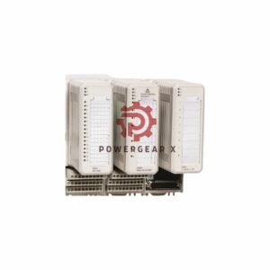
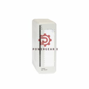
KFD2-VR4-EX1.26 Voltage Repeater – Precision Signal Isolation for Hazardous Areas
This 1‑channel isolated barrier converts vibration sensor inputs into a stable 0 V … −20 V output. It powers field devices, handles negative voltage signals, and meets SIL 2 safety standards. Designed for DIN‑rail mounting, it ensures reliable signal transmission in demanding industrial environments.
Key Features – MECE Classified
- Function & Signal Type
- Analog input barrier for voltage signals
- Input range: 0 V … −20 V (transmission range)
- Output: 0 V … −20 V (load ≥9 kΩ for 3‑wire, ≥2 kΩ for 2‑wire)
- Cut‑off frequency: 10 kHz (−0.1 dB) / 20 kHz (−1 dB)
- DC transfer error <10 mV (with 10 kΩ load)
- Power Supply & Consumption
- Rated voltage: 19 … 30 V DC (via Power Rail or terminals 11+/12‑)
- Power dissipation ≤1.2 W, consumption ≤1.6 W
- Functional insulation output/power supply (50 V AC)
- Performance & Accuracy
- Input resistance: 10 kΩ (terminals 4‑common, 6‑/2‑)
- Output resistance: 24 Ω typ. (27 Ω max)
- Temperature drift <100 ppm/K
- Ripple: <20 mVrms (200 kHz), <3 mVrms (20 kHz)
- Time delay: 7.1 ±0.3 µs
- Environmental & Mechanical
- Ambient temperature: −20 … +60 °C
- Protection: IP20 (housing), mounting on 35 mm DIN‑rail
- Dimensions: 20 x 119 x 115 mm, mass approx. 125 g
- EMC: EN 61326‑1:2013 (industrial locations)
- Safety & Hazardous Area Approvals
- SIL 2 acc. to IEC/EN 61508
- ATEX: Ⅱ (1)G [Ex ia Ga] IIC, Ⅱ (1)D [Ex ia Da] IIIC, Ⅰ (M1) [Ex ia] I
- IECEx: [Ex ia Ga] IIC, [Ex ia Da] IIIC, [Ex ia Ma] I; Ex nA II T4 Gc
- UL/cULus: Control drawing 116‑0316
- Galvanic isolation: 375 V peak (input/output, input/power)
Technical Data – at a Glance
- Brand: Pepperl+Fuchs
- Model: KFD2‑VR4‑EX1.26
- Series: K‑System (isolated barriers)
- Input: 0 … −20 V (vibration sensors)
- Output: 0 … −20 V (load ≥2 kΩ)
- Frequency response: 10 kHz (−0.1 dB)
- Sensitivity: full span 20 Vpp (sine wave)
- Linearity: DC error <10 mV
- Resolution: not specified (analog continuous)
- Temperature range: −20 … +60 °C
- Environmental tolerance: IP20, EMC compliant
- Noise immunity: ripple <20 mVrms (200 kHz)
Installation & Mounting
- Snap onto 35 mm DIN‑rail per EN 60715
- Use terminals 4 (common), 1,3,5 (supply‑), 2,6 (signal‑) for field side
- Control side: terminals 7‑ and 8+ for output
- Power via Power Rail or terminals 11+/12‑
- Observe safe maximum voltage Um = 253 V (input/output)
Commissioning & Maintenance Ease
- LED indicator for operating status
- Front labelling space for easy identification
- Screw terminals for secure wiring
- No routine calibration needed – drift <100 ppm/K
- Compact housing (B2) saves cabinet space
Compatibility & Accessories
- Works with 2‑wire and 3‑wire vibration sensors
- Power feed module: KFD2‑EB2(.R4A.B)(.SP)
- Universal power rail: UPR‑03(‑M)(‑S)
- Profile rail: K‑DUCT‑BU(‑UPR‑03)
- Compatible with most PLC analog input cards (0 … −20 V)
Certifications & Compliance
- ATEX: BAS 02 ATEX 7206, DMT 01 ATEX E 133, TÜV 99 ATEX 1499 X
- IECEx: BAS 05.0078, BAS 10.0085X
- UL: cULus (Control drawing 116‑0316)
- SIL 2 acc. to IEC/EN 61508
- EN 60079‑0:2012+A11:2013, EN 60079‑11:2012, EN 60079‑15:2010
Package Contents
- 1 x KFD2‑VR4‑EX1.26 Voltage Repeater
- 1 x terminal label set
- Instruction manual (digital download)
- Mounting accessories (DIN‑rail clips included)
Warranty & Shipping
- 12‑month warranty against manufacturing defects
- Same‑day dispatch (order before 2 PM UTC+8)
- Shipping: FedEx, UPS, DHL – tracking provided
- Estimated delivery: 12‑24 hours (domestic), 2‑5 days (international)
Expert Review – Manager’s Insight
“The KFD2‑VR4‑EX1.26 stands out for its ultra‑low output resistance (24 Ω) and fast 7 µs response – critical for vibration monitoring in turbines and compressors. Its SIL 2 rating and ATEX/IECEx approvals make it a safe choice for Zone 0/1 applications. We recommend pairing it with the UPR‑03 power rail for clean, distributed power. A reliable workhorse for critical signal chains.”
Typical Applications & Compatible Devices
- Vibration monitoring on motors, pumps, and fans
- Speed sensors (proximity probes) in hazardous areas
- Connecting IEPE/charge amplifiers to PLC/DCS
- Signal conditioning for accelerometers (100 mV/g)
- Use with Pepperl+Fuchs K‑System power supplies and termination boards
Frequently Asked Questions (FAQ)
- What is the input voltage range?
- 0 V to −20 V (negative signal).
- Can I use it with a 2‑wire sensor?
- Yes, minimum load is 2 kΩ for 2‑wire sensors.
- Is it suitable for SIL 2 loops?
- Yes, it meets SIL 2 per IEC/EN 61508.
- What is the maximum output current?
- It supplies >10 mA at −21 V (terminals 4‑5).
- Does it require external power?
- Yes, 19‑30 V DC via Power Rail or terminals.
- How do I mount it?
- Snap onto 35 mm DIN‑rail (EN 60715).
- Experience: What about AC superimposed signals?
- AC components up to 20 Vpp (sine) are acceptable without errors.
- Selection guide: Which model for 4‑20 mA?
- This is voltage‑only; use KFD2‑CD‑Ex series for current.
Selection Guide – Quick Advice
- Choose this unit if your sensor outputs negative voltage (0 … −20 V).
- For positive voltage signals, select KFD2‑VR‑Ex1.2x series.
- Need isolated power for the sensor? This barrier provides field supply.
- For higher channel count, use KFD2‑VR4‑EX1.26 with UPR‑03 rail.
- Always verify load impedance (≥9 kΩ for 3‑wire, ≥2 kΩ for 2‑wire).
For inquiries: sales@powergearx.com | +86 18030005825 (WhatsApp)
Copyright © 2026 Powergear X Automation Limited. All rights reserved.
Original Source: https://www.powergearx.com/




There are no reviews yet.